 English
 中文简体
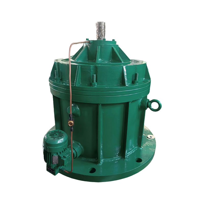
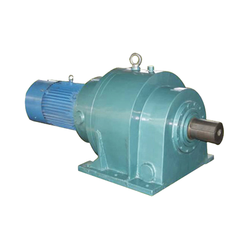
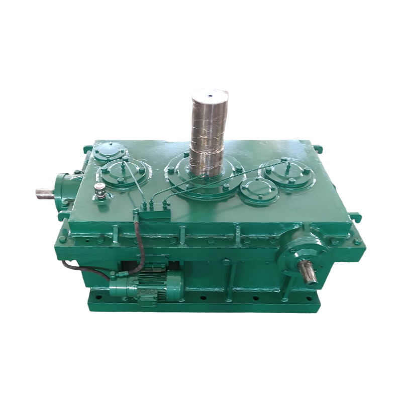
中文简体A gear reducer is a mechanical device that uses a set of gears to decrease the rotational speed of a motor while proportionally increasing its output torque. It sits between an electric motor and the driven machinery, converting high speed, low torque input into low speed, high torque output that industrial equipment actually needs to move heavy loads. Without a gear reducer, most standard electric motors would spin far too fast and lack the torque required to drive conveyors, mixers, cranes, or pumps efficiently.
This article explains how a gear reducer works, the main types available, how to calculate reduction ratio, typical cost ranges, efficiency comparisons, and the key factors engineers and buyers should evaluate before selecting one for an application.
Content
- 1 Quick Answer: Why Gear Reducers Matter
- 2 How a Gear Reducer Works
- 3 Main Types of Gear Reducers
- 4 Gear Reducer Cost Overview
- 5 Key Factors When Selecting a Gear Reducer
- 6 Common Industrial Applications
- 7 Gear Reducer Maintenance and Lifespan
- 8 Gear Reducer vs Gearbox: Is There a Difference?
- 9 Frequently Asked Questions
- 9.1 What is the main purpose of a gear reducer?
- 9.2 How do I calculate the reduction ratio I need?
- 9.3 Which gear reducer type is the most efficient?
- 9.4 Can a gear reducer be used to increase speed instead of reducing it?
- 9.5 How often should gear reducer oil be changed?
- 9.6 What size gear reducer do I need for my application?
- 10 Final Takeaway
Quick Answer: Why Gear Reducers Matter
A gear reducer matters because it allows a small, fast, cost effective motor to produce the high torque needed for heavy industrial work without oversizing the motor itself. Standard AC induction motors commonly operate at 1,750 or 3,450 revolutions per minute, speeds that are far too high for most mechanical equipment, so a reducer scales that speed down to a usable range, often between 5 and 500 revolutions per minute, while multiplying the available torque.
According to the American Gear Manufacturers Association, properly matched gear reducers can improve overall drivetrain efficiency and significantly extend equipment service life by reducing mechanical stress on downstream components (Source: American Gear Manufacturers Association, Gear Technical Standards).
How a Gear Reducer Works
A gear reducer works by meshing a small input gear with a larger output gear, so that each rotation of the input shaft only partially rotates the output shaft, trading rotational speed for mechanical force. This relationship follows a straightforward physical principle: torque and speed are inversely proportional across a gear set, meaning as speed decreases, torque increases by roughly the same ratio, minus mechanical losses from friction and gear meshing.
Understanding the Reduction Ratio
The reduction ratio is the single most important number when selecting a gear reducer, since it defines exactly how much the output speed drops and torque increases relative to the input. A reduction ratio of 10:1 means the output shaft turns once for every ten turns of the input shaft, while torque at the output increases by approximately ten times, before accounting for efficiency losses.
| Reduction Ratio | Input Speed (RPM) | Output Speed (RPM) | Approximate Torque Multiplier |
| 5:1 | 1,750 | 350 | Approximately 5x |
| 10:1 | 1,750 | 175 | Approximately 10x |
| 30:1 | 1,750 | 58 | Approximately 30x |
| 60:1 | 1,750 | 29 | Approximately 60x |
Main Types of Gear Reducers
The five most common gear reducer types are worm, helical, planetary, bevel, and cycloidal, and each is suited to different combinations of load, speed, precision, and space requirements. Choosing the wrong type for an application is one of the most frequent causes of premature drivetrain failure in industrial settings.
Worm Gear Reducers
Worm gear reducers use a screw shaped worm gear meshed with a toothed wheel to achieve high reduction ratios in a compact right angle design. They are valued for smooth, quiet operation and inherent self locking ability, which prevents the output shaft from back driving under load, making them popular in lifting and holding applications. Their main drawback is lower mechanical efficiency, typically ranging from 50 to 90 percent depending on the ratio, compared to other gear types.
Helical Gear Reducers
Helical gear reducers use angled gear teeth that engage gradually, resulting in smoother operation, higher load capacity, and greater efficiency than worm designs. Efficiency for a single stage helical reducer commonly reaches 94 to 98 percent, making it a preferred choice for continuous duty applications such as conveyor systems and mixers where energy costs matter over long operating hours (Source: American Gear Manufacturers Association, Gear Efficiency Standards).
Planetary Gear Reducers
Planetary gear reducers arrange multiple small gears around a central sun gear inside an internal ring gear, allowing them to deliver very high torque density in a compact housing. This design distributes load across multiple gear contact points simultaneously, which is why planetary reducers are widely used in robotics, precision automation, and applications where space is limited but torque demands are high.
Bevel Gear Reducers
Bevel gear reducers use cone shaped gears to transmit motion between shafts positioned at an angle, most commonly a 90 degree right angle configuration. They are frequently chosen when the driven equipment requires a direction change without the added friction losses associated with worm gear designs.
Cycloidal Gear Reducers
Cycloidal gear reducers use an eccentric cam and disc mechanism instead of conventional meshing teeth, giving them exceptional shock load resistance and near zero backlash. This makes them especially suitable for applications with sudden load changes, such as material handling equipment exposed to frequent starts, stops, and impact loading.
| Type | Typical Efficiency | Self Locking | Best Application |
| Worm | 50 percent to 90 percent | Yes | Lifts, hoists, right angle drives |
| Helical | 94 percent to 98 percent | No | Conveyors, mixers, continuous duty |
| Planetary | 90 percent to 98 percent | No | Robotics, automation, compact drives |
| Bevel | 92 percent to 97 percent | No | Right angle drives, agricultural equipment |
| Cycloidal | 90 percent to 95 percent | No | Shock loading, material handling |
Gear Reducer Cost Overview
Gear reducer prices typically range from $150 for small worm gear units to over $10,000 for large industrial planetary or helical bevel units, depending on torque capacity, ratio, and precision requirements. Buyers should factor in not just the purchase price but also long term energy costs, since a lower efficiency reducer can cost significantly more to operate over its service life.
- Small worm gear reducers: Typically $150 to $600, used for light duty conveyors and packaging equipment.
- Mid size helical gear reducers: Typically $500 to $3,000, used for general industrial drives.
- Planetary gear reducers: Typically $300 to $5,000, used for precision automation and robotics.
- Large industrial bevel or helical bevel units: Typically $2,000 to $12,000 or more, used for heavy machinery and mining equipment.
Key Factors When Selecting a Gear Reducer
Selecting the right gear reducer requires matching torque, speed, mounting configuration, and duty cycle to the specific demands of the driven equipment, since an undersized unit will fail prematurely while an oversized unit wastes money and space. Engineers typically evaluate a checklist of criteria before finalizing a selection.
- Required output torque: Calculate the torque needed by the driven load, including starting torque, which is often higher than running torque.
- Reduction ratio: Determine the ratio needed to bring motor speed down to the target output speed for the application.
- Service factor: Apply a safety margin based on duty cycle, shock loading, and expected operating hours per day.
- Mounting configuration: Confirm whether the application needs an inline, right angle, or shaft mounted design to fit existing equipment.
- Environmental conditions: Account for temperature extremes, moisture exposure, or dust that could affect lubrication and seal performance.
- Efficiency requirements: Weigh upfront cost against long term energy savings, especially for continuous duty applications running many hours per day.
Common Industrial Applications
Gear reducers are used across nearly every heavy industry, from material handling to agriculture, wherever a motor's natural speed and torque output do not match the mechanical demands of the equipment. Understanding real world use cases helps illustrate why the right selection matters so much.
- Conveyor systems: Helical or shaft mounted reducers control belt speed precisely while handling continuous duty cycles in warehouses and manufacturing plants.
- Cranes and hoists: Worm or planetary reducers provide the self locking safety and high torque needed to lift and hold heavy loads securely.
- Mixers and agitators: Helical or bevel helical reducers deliver steady torque for viscous material processing in food and chemical production.
- Agricultural machinery: Bevel gear reducers redirect power at right angles to drive rotary equipment such as tillers and irrigation pumps.
- Robotics and automation: Compact planetary reducers provide the precise, high torque, low backlash motion control required for robotic arms and positioning systems.
Gear Reducer Maintenance and Lifespan
Proper lubrication and regular inspection are the two biggest factors determining how long a gear reducer lasts, with well maintained industrial units commonly reaching 15 to 20 years of service life. Neglected lubrication is consistently cited by industry engineering studies as the leading cause of premature gear failure, often producing excessive heat, pitting, and eventual tooth breakage.
Recommended Maintenance Practices
Following a consistent maintenance schedule significantly reduces unplanned downtime and extends the operational life of a gear reducer. Industrial reliability engineering guidance generally recommends the following practices.
- Check lubricant levels monthly and replace oil according to the manufacturer's recommended interval, typically every 2,500 to 8,000 operating hours.
- Monitor operating temperature since sustained temperatures above the rated limit indicate a lubrication or overload problem.
- Inspect for unusual vibration or noise which often signals bearing wear or gear tooth damage before catastrophic failure occurs.
- Check seal integrity regularly to prevent contamination from moisture or dust entering the gear housing.
- Verify shaft alignment during installation and after any maintenance work, since misalignment accelerates bearing and gear wear.
Gear Reducer vs Gearbox: Is There a Difference?
A gear reducer is technically a specific type of gearbox designed only to reduce speed and increase torque, while the broader term gearbox can also include units that increase speed or simply change direction without altering the ratio. In everyday industrial usage the terms are frequently used interchangeably, but understanding the distinction helps when reading technical specifications or comparing quotes from equipment suppliers.
Frequently Asked Questions
What is the main purpose of a gear reducer?
The main purpose of a gear reducer is to lower motor output speed while increasing torque so that industrial equipment can operate at the correct speed with sufficient force to move its intended load. This allows standard motors to power a much wider range of machinery than they could drive directly.
How do I calculate the reduction ratio I need?
The reduction ratio needed is calculated by dividing the motor's input speed by the desired output speed of the driven equipment. For example, a motor running at 1,750 RPM that needs to drive equipment at 35 RPM requires a reduction ratio of approximately 50 to 1.
Which gear reducer type is the most efficient?
Helical gear reducers are generally the most efficient type, commonly reaching 94 to 98 percent efficiency, compared to worm gear reducers which can drop as low as 50 percent at high ratios. Higher efficiency translates directly into lower energy costs over the life of the equipment.
Can a gear reducer be used to increase speed instead of reducing it?
Yes, running a gear reducer in reverse can increase output speed, though this reduces available torque and is generally referred to as a speed increaser rather than a standard reducer application. Not all gear reducers are rated for this reverse operation, so manufacturer specifications should always be checked first.
How often should gear reducer oil be changed?
Gear reducer oil should typically be changed every 2,500 to 8,000 operating hours depending on load conditions, operating temperature, and the type of lubricant used. Units operating in high temperature or heavy load environments generally require more frequent oil changes than lightly loaded units.
What size gear reducer do I need for my application?
The correct size depends on the required output torque, reduction ratio, and service factor for the specific load and duty cycle, which is why manufacturers publish detailed selection charts based on horsepower and torque ratings. Consulting these charts or a qualified engineer before purchasing helps avoid undersizing or oversizing the unit.
Final Takeaway
A gear reducer is an essential mechanical component that converts high speed, low torque motor output into the low speed, high torque power that industrial equipment needs to operate reliably. Choosing the right type, whether worm, helical, planetary, bevel, or cycloidal, along with correctly matching the reduction ratio, torque rating, and maintenance schedule to the application, directly affects equipment performance, energy costs, and long term service life. Careful selection upfront, guided by manufacturer specifications and established industry standards, remains the most reliable way to avoid costly downtime and premature failure.