 English
 中文简体
A helical bevel gear reducer is a right-angle gearbox that pairs a bevel gear set with helical gearing. The bevel stage turns the drive through 90 degrees; the helical stage then multiplies torque with high efficiency and low noise. If you have to transmit power around a corner — on a conveyor drive, a crane travel unit, an agitator or a mill — this is normally the family of unit you want, provided the torque, service factor and thermal rating match the real duty cycle.
The short answer to the question buyers ask most often, "helical bevel or worm gear?", is that the helical bevel unit wins on efficiency, load capacity and service life, while the worm unit wins on first cost and self-locking behaviour. Everything below is about how that trade-off looks in real numbers.
Content
- 1 What Is Inside a Helical Bevel Gear Reducer?
- 2 Helical Bevel vs Worm Gear vs Planetary Reducers
- 3 How to Size a Helical Bevel Gear Reducer
- 4 Specification Checks Before Ordering
- 5 Where Helical Bevel Gear Reducers Are Used
- 6 Matching the Unit to the Driven Machine
- 7 Procurement Risks Worth Pricing In
- 8 Frequently Asked Questions
What Is Inside a Helical Bevel Gear Reducer?
A helical bevel gear reducer contains two reduction stages in series: a bevel pinion and bevel gear on the input side, followed by one or more helical gear stages on the output side. That layout is why the unit is often called a right-angle helical or bevel-helical gearbox.
The bevel stage
The bevel stage makes the 90-degree turn. In modern units the bevel gears are ground and lapped in pairs and carried on rigid, well-supported shafts. This stage decides how quiet and how durable the gearbox stays at high input speed.
The helical stage
The helical stage does the torque multiplication. Because helical teeth engage gradually instead of all at once, load is shared across several teeth at any moment, which cuts noise, shock loading and tooth stress. A well-made two- or three-stage unit typically reaches 94% to 97% efficiency per stage at rated load.
Three practical consequences follow from that design:
- Higher efficiency than a worm gearbox of similar torque, which reduces motor size and energy cost.
- Higher permissible output torque for the same frame size, because load is spread over more teeth.
- No self-locking, so a brake or backstop may be needed on inclined conveyors and hoists.
Helical Bevel vs Worm Gear vs Planetary Reducers
Comparing four or five parameters at once is far more useful than comparing catalogue adjectives. The table below summarises the differences that actually decide a selection.
| Parameter | Helical bevel | Worm gear | Planetary |
|---|---|---|---|
| Efficiency at rated load | 94–97% per stage | 60–90%, falling at high ratio | 94–97% per stage |
| Output shaft direction | 90 degrees to input | 90 degrees to input | In line with input |
| Ratio per stage | About 1:1 to 1:6 | About 1:5 to 1:100 | About 1:3 to 1:10 |
| Self-locking | No | Often, at high ratio | No |
| Best fit | Right-angle drives with heavy torque and long duty | Low power, intermittent duty, tight budget | Compact coaxial drives needing high ratio |
If the layout needs a right-angle drive and the duty is continuous, the helical bevel unit is the default choice. If the load must hold itself when the motor stops, a worm gearbox may still be the cheaper answer.
How to Size a Helical Bevel Gear Reducer
Sizing is a five-step calculation, and the order matters: get the duty cycle right first, because every later number depends on it.
- Establish the real load torque at the output shaft in Nm, including starting torque and any jam condition.
- Determine the required output speed and the resulting ratio, then pick the closest standard ratio rather than a special one.
- Apply a service factor for the driven machine: typically 1.25 to 1.5 for uniform loads such as conveyors, and 1.75 to 2.0 or more for crushers, mixers and reversing mill drives.
- Check thermal capacity, not only mechanical torque. A unit that is mechanically adequate can still overheat in slow, heavily loaded, poorly ventilated service.
- Check the mechanical interface: shaft diameter and keyway, mounting position, oil level plugs, breather position and available cooling.
Two numbers are routinely underestimated. The first is starting torque — an induction motor switched directly on line can briefly deliver two to three times rated torque, and that peak passes straight through the gearbox. The second is radial load on the output shaft, which is set by the sprocket, pulley or pinion mounted on it, not by the gearbox itself.
Specification Checks Before Ordering
Confirm these six items on the data sheet before the order is released. A unit quoted at a different output speed is effectively a different gearbox, so tolerance and speed have to be agreed in writing.
| Parameter | What to confirm | Why it matters |
|---|---|---|
| Rated output torque | Nm at the required output speed | Torque and speed are linked; a ratio change changes the duty |
| Service factor | 1.25–1.5 uniform load, 1.75–2.0 or higher with shock | Sets the margin against fatigue and bearing wear |
| Thermal capacity | kW at the site ambient temperature | Slow, heavily loaded units can overheat even when mechanically adequate |
| Ratio and backlash | Nominal ratio, backlash in arc-minutes | Drives positioning accuracy, noise and load sharing |
| Mounting position | M1 to M6 or equivalent | Decides oil level and how well the bearings are lubricated |
| Input interface | IEC or NEMA motor flange, or solid input shaft | Determines whether an existing motor can be reused |
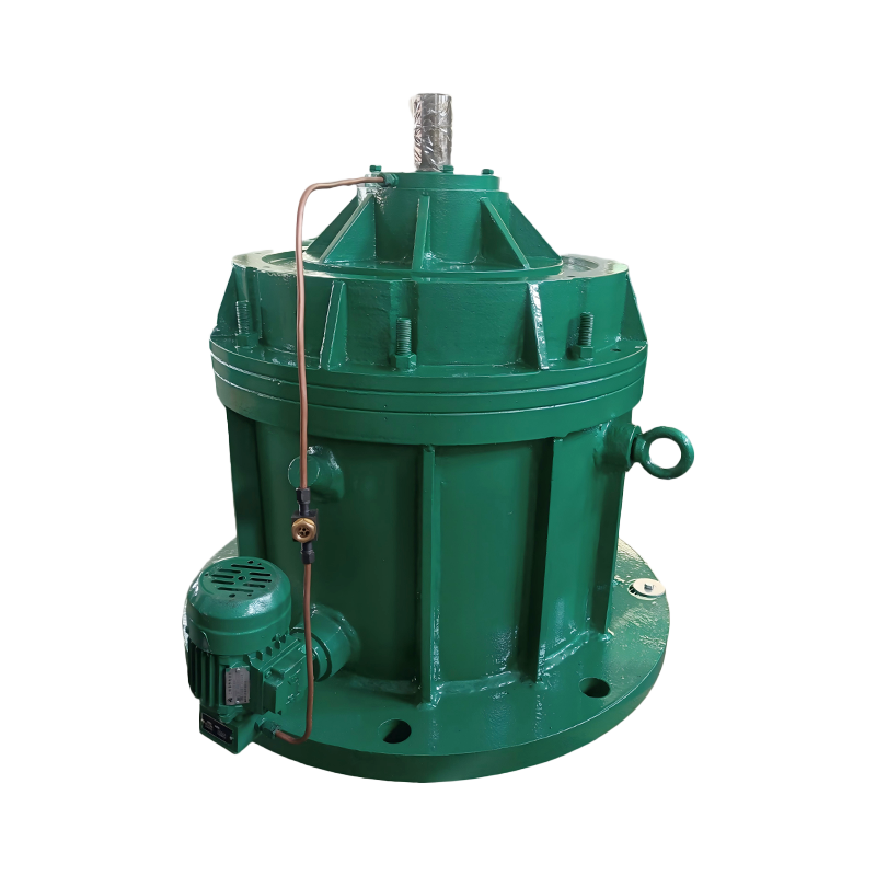
Where the required output torque sits beyond a standard catalogue size, a modular heavy-duty gearbox lets the stage combination and housing be re-staged instead of forcing a compromised ratio into a standard unit.
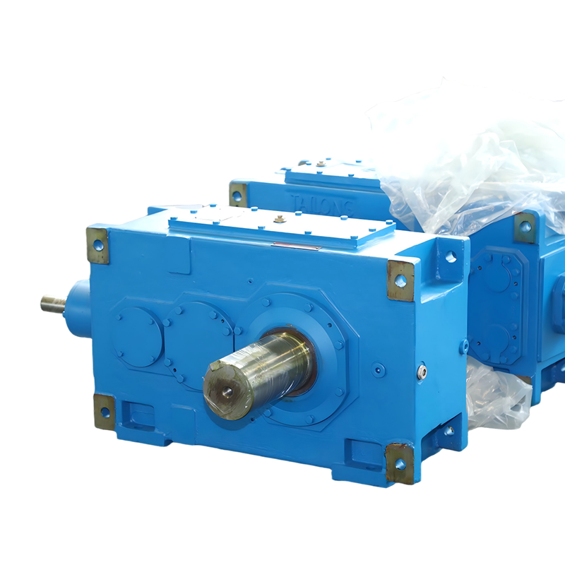 Modular Heavy-Duty Gearbox for Industrial Drive SystemsA modular transmission core with interchangeable input, reduction and output modules, re-staged for high-torque duties instead of a compromised standard unit.View Product →
Where Helical Bevel Gear Reducers Are Used
Right-angle bevel-helical drives appear wherever torque has to be turned through 90 degrees and then carried for years with little attention.
- Bulk material handling: belt and chain conveyors, bucket elevators, stacker and reclaimer travel and slewing drives.
- Metallurgy: rolling mill auxiliaries, ladle turret rotation, tension levelers and pipe piercing mills.
- Cranes and lifting: hoist, trolley and bridge travel drives, gate hoists and winches.
- Processing: mixers and agitators, extruders, kiln and mill auxiliaries.
- Power and water: cooling tower fans, scrapers and clarifier drives.
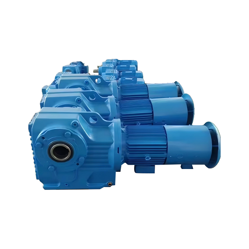 Integrated Helical Gear Reduction Motor with FlangeAn integrated helical drive package combining motor and gearbox, suited where alignment, sealing and warranty responsibility should stay with a single supplier.View Product →
Where the drive arrives as one package, a helical gear reduction motor with an integrated flange keeps alignment, sealing and warranty responsibility in a single place rather than split between two suppliers.
Matching the Unit to the Driven Machine
The driven machine, not the gearbox catalogue, sets the service factor. Crane and hoist duty is the clearest example, because reversing operation and load reversal both stress the same gear flanks from two directions.
- Crane travel and hoist drives: frequent starts, high inertia and reversing load usually push the service factor above 1.75.
- Conveyors and elevators: uniform load, but the cold start with a loaded belt is the design case.
- Mixers and mills: shock loading plus high radial load on the output shaft.
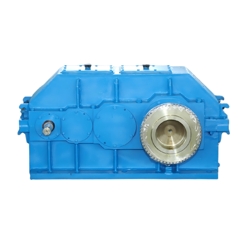 Hardened Gear Reducer for Crane Hoisting and TravelA crane-duty reducer with hardened gears and heavy-duty structure, engineered for frequent starts, impact loads and precise positioning in lifting mechanisms.View Product →
A hardened-tooth unit built specifically for crane duty is usually cheaper over ten years than a general-purpose gearbox run at its limit, simply because bearing and seal replacement intervals are longer.
Procurement Risks Worth Pricing In
Most field failures are not manufacturing defects; they are mismatches between the specified duty and the installed duty. Those mismatches are predictable and can be priced before the order is placed.
- Selecting on torque alone with a service factor of 1.0, leaving no margin for the first cold start of a loaded conveyor.
- Ignoring ambient conditions: above roughly 40 °C, or in dusty enclosures, thermal capacity is the binding limit, not tooth strength.
- Overlooking back-driving. A helical bevel unit will be driven backwards by an inclined load, so a brake or backstop must be specified.
- Buying on price per kilogram. Two units of the same mass can differ considerably in bearing life and in the gear accuracy that controls noise.
- Forgetting the spares path: shaft seals, bearings and replacement gears must be available for the frame sizes actually installed.
This is where manufacturing depth shows up in practice. A plant that machines its own large gears on equipment such as 3 m gear grinders and 3.2 m hobbing machines can hold accuracy on big, low-volume units and respond faster when a non-standard ratio is needed — which is the usual situation on retrofit projects. For background on how the different reducer families compare before you commit, this walkthrough of how industrial gear reducers work is a useful starting point.
Frequently Asked Questions
What is the difference between a helical bevel and a helical inline reducer?
Only the input arrangement differs. A helical inline unit has its input and output shafts on the same axis; a helical bevel unit turns the drive through 90 degrees first and then reduces it. Torque capacity and efficiency are comparable when both are sized to the same service factor.
Can a helical bevel gear reducer be mounted in any position?
No. Mounting position determines the oil level and which bearings sit in the oil bath. Positions are normally designated M1 to M6, and the unit is filled and the breather fitted for one of them. Changing position after delivery usually means changing the oil fill level.
Is a helical bevel gear reducer self-locking?
Generally not. It can be back-driven by the load, so inclined conveyors, hoists and any application where the load must hold position need a brake, backstop or holding device.
How long should a helical bevel gear reducer last?
With correct selection, clean oil and service at the recommended intervals, 10 to 20 years is realistic for continuous industrial duty. The dominant variables are thermal load, lubricant condition and how accurately the driven machine is aligned to the output shaft.
To sum up: choose a helical bevel gear reducer when the drive must turn 90 degrees and carry heavy torque continuously; size it on real load torque, an honest service factor and thermal capacity rather than on nominal torque alone; and confirm ratio, mounting position and input interface in writing before the order is released. Handle those three points and the gearbox becomes the least interesting — and least expensive — part of the drive train.