 English
 中文简体
A gear reducer motor is a motor paired with a gearbox so that the package delivers low output speed and high output torque from a single drive unit. The motor supplies the power, the reducer trades speed for torque, and the output shaft turns the machine slowly but with enough force to move a loaded conveyor, rotate a mill, or lift a crane load.
The term is used loosely, and that causes real problems at the procurement stage. Some suppliers mean an integrated gearmotor: one housing, one shaft, one nameplate. Others mean a standard motor plus a separate reducer that you couple and align on site. Both are common in heavy industry, and the difference changes how you size the drive, how you install it, and what you keep on the shelf as a spare.
Content
What a Gear Reducer Motor Does
A gear reducer motor trades speed for torque through a gear train, and the trade stays close to linear until efficiency losses and thermal limits take over. If the motor turns at n1 rpm and the gearbox ratio is i, output speed is n2 = n1 / i, while output torque rises roughly in proportion to i, minus mechanical losses.
A worked example shows the value. A four-pole motor running at 1470 rpm coupled to a 20:1 helical reducer gives about 73.5 rpm at the output shaft. If the motor delivers 100 N·m at its shaft and the gear train runs at 96% efficiency, the output shaft carries roughly 100 x 20 x 0.96 = 1920 N·m. A small, fast, inexpensive motor is doing the work of a very large slow one.
Typical duties include belt and screw conveyors, ball and roller mills, crane travel and hoist drives, mixers, feeders, cooling tower fans and metal processing lines. In every case the driven machine needs high torque at low speed, and driving it directly would demand an impractical motor size and starting current.
Integrated Gearmotor or Separate Motor and Reducer?
Choose an integrated gearmotor when space is tight, factory alignment matters, and the duty is repeatable and catalog-sized. Choose a separate motor and reducer when the motor is large, when a standard IEC frame must be sourced locally, or when the reducer is the engineered item and the motor is a commodity.
- Integrated gearmotor: one shaft, factory-aligned, compact, simpler spares — but replacing either half means replacing the whole unit.
- Separate motor and reducer: flexible motor sourcing, faster motor swap, easier upgrade to inverter duty — but you own the alignment, the coupling and the concentricity check.
Gear Types Used in Gear Reducer Motors
Four gear types cover most industrial gear reducer motors: helical gears for general continuous duty, planetary gears for high torque in a small envelope, worm gears for high ratios and self-locking, and cycloidal pinwheel gears for shock loads and compact inline drives. Match the type to the duty first and compare price second; if you want the underlying principle, our explanation of how industrial gear reducers work and which type suits a given duty is a useful starting point.
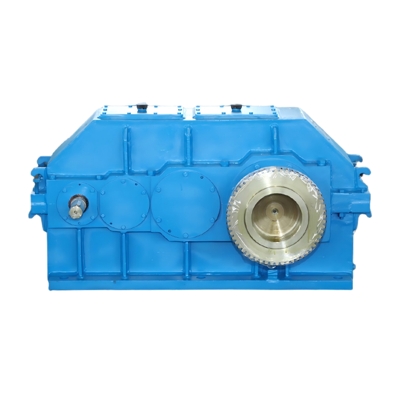
Helical and cylindrical gear reducers are the default for continuous duty at moderate to high power, because parallel-shaft helical teeth reach 96–98% efficiency per stage. Multi-stage units cover several hundred to one; the penalty for a high ratio is housing length and weight rather than efficiency. They are the usual choice for conveyors, mills, mixers and process lines.
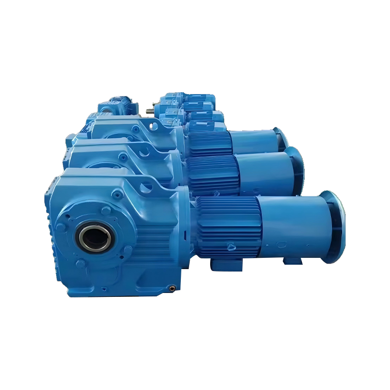 Helical Gear Reduction Motor for Continuous Duty Industrial DrivesIntegrated helical gearmotor delivering high-efficiency, low-noise transmission, suited to conveyors, mills, mixers and process lines where parallel-shaft reducers are common.View Product →
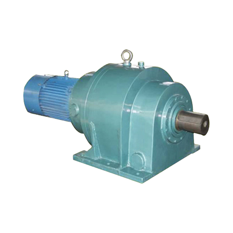
Planetary gear reducers share the load across three or more planet gears, which is why they deliver very high torque density in a coaxial package. Ratios run from about 3:1 per stage to 1000:1 in multi-stage builds, at 96–97% efficiency, and they suit roller presses, winches, travel drives and mixers where axial length is limited.
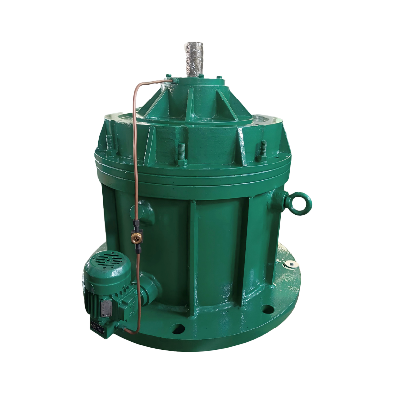 Planetary Gear Reducers for High Torque Density Coaxial Drive SystemsCoaxial planetary reducers offer high torque density and efficiency, ideal for compact, heavy-duty applications such as robots, wind power and construction machinery.View Product →
Worm gear reducers give a right-angle drive, a high ratio in a single stage and quiet running, but efficiency falls from roughly 90% at low ratios to below 60% at high ratios, and heat becomes the limiting factor. Enveloping designs wrap the worm with the gear to raise load capacity and smooth the tooth contact.
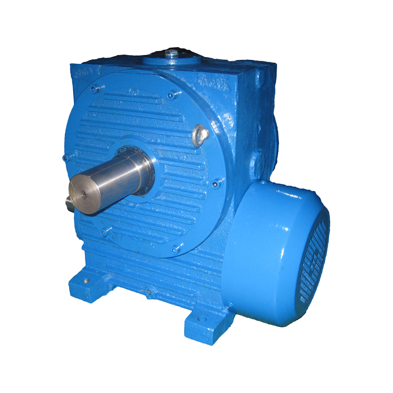 Double-Enveloping Worm Gear Reducer for Heavy-Load Low-Speed ApplicationsDouble-enveloping worm gear reducer provides larger meshing area, higher load capacity and longer life for precise low-speed, heavy-load industrial drives.View Product →
Cycloidal pinwheel reducers use rolling contact instead of sliding teeth, so they absorb shock loads well. Typical ratios sit between 9:1 and 87:1, and they are common on feeders, hoists, mixers and other drives that see frequent starts or impact.
| Gear type | Typical ratio | Efficiency | Best fit | Watch out for |
|---|---|---|---|---|
| Helical / cylindrical | 2:1 to 500:1, multi-stage | 96–98% per stage | Continuous duty conveyors, mills, mixers | Longer, heavier housing as ratio rises |
| Planetary | 3:1 per stage, to 1000:1 | 96–97% | High torque in a short axial length | Higher cost, tighter manufacturing tolerance |
| Worm (single or double enveloping) | 5:1 to 100:1 | 90% down to below 60% | High ratio, quiet, right-angle, self-locking | Heat generation, strict oil grade and level |
| Cycloidal pinwheel | 9:1 to 87:1 | 90–95% | Shock loads, frequent starts, compact drives | Less suited to sustained very high speed input |
The Numbers That Decide Whether the Unit Survives
Output torque, service factor and thermal capacity decide whether a gear reducer motor survives in service; the motor power rating on its own does not. Check these items before you sign off:
- Output torque, not motor kilowatts. The same motor behind a 10:1 and a 40:1 reducer gives very different shaft torque, so size the reducer against the torque the machine actually needs.
- Service factor. Around 1.0 for uniform loads such as fans, 1.25–1.5 for moderate shock, and 1.75–2.0 for heavy shock such as crushers, mills and crane hoists, where starting torque can exceed twice running torque.
- Thermal capacity and duty cycle. Intermittent duty allows a smaller frame than continuous duty; confirm the permissible ambient temperature, typically 40 °C for standard units, and check oil temperature in the field.
- Radial and axial shaft loads. A sprocket or pulley on the output shaft adds an overhung load that the bearings must carry; it is a separate limit from torque.
- Backlash. Conveyors tolerate generous backlash, while indexing, positioning and reversing drives usually do not.
- Mounting position and lubrication. Oil level, breather and seal orientation change with mounting position, so a horizontal unit cannot simply be turned on its side.
How to Select a Gear Reducer Motor in Five Steps
Work backwards from the driven machine and confirm five items before ordering: required torque, required speed, service factor, mechanical interface and environment.
- Define the duty. Record torque and speed at the machine shaft, and state whether the load starts empty, loaded, or against a full head of material.
- Convert to design torque. Multiply running torque by the service factor, then check starting torque and the inertia of the driven mass.
- Choose the ratio and verify the speed tolerance. A conveyor may accept a few percent either way; a screw feeder, a weighing feeder or a mill usually cannot.
- Check the mechanical limits. Output shaft diameter, keyway, permitted overhung load, mounting position, and whether a backstop or brake is needed.
- Confirm the interface and environment. Motor frame, voltage, enclosure, cooling method, ambient temperature, altitude and the lubrication schedule.
Installation and Running Checks That Prevent Early Failure
Misalignment, wrong oil and loose fasteners cause more early failures than genuine overload, so treat the first week of running as part of the specification. A practical check list:
- Ensure concentricity between the motor shaft and reducer input shaft within the coupling maker's tolerance; angular misalignment destroys seals and bearings quickly.
- Fill to the oil grade and level specified for the actual mounting position, and verify that the breather sits where the design expects it.
- Re-check foundation bolts and the output coupling after the first shift, then again after the first week.
- Take a vibration and temperature baseline during the first 100 hours, and change the oil after the initial run-in period.
Common Mistakes and Procurement Risks
Most specification-stage failures come from sizing on motor kilowatts alone, ignoring starting torque, and assuming that mounting position is interchangeable. The recurring risks are predictable:
- Buying by ratio only, with no stated service factor or duty cycle.
- Assuming a larger motor solves a torque, thermal or bearing problem.
- Omitting overhung load data for sprockets, pulleys, brakes or brakes with a lever arm.
- Ordering a standard foot, flange or shaft interface for a non-standard machine.
- Leaving spares, lead time and oversized or non-standard castings until after the order is placed.
Manufacturing depth reduces several of these risks at once. Taixing Reducer Co., Ltd., for example, has built industrial gear reducers since 1984, lists 16 product series and more than 10,000 specifications, and reports an annual capacity of 200,000 reducers, backed by large gear grinding and hobbing equipment for oversized and non-standard units.
FAQ
Is a gear reducer motor the same as a gearmotor?
In everyday use, yes — both mean a motor and gearbox delivering reduced speed. Strictly, a gearmotor is normally one integrated housing, while the broader term also covers a separate motor coupled to a reducer.
Does a higher ratio always give more usable torque?
No. Torque rises with ratio, but efficiency and thermal capacity fall, so beyond the point where heat cannot leave the housing, extra ratio adds losses rather than usable output.
Can I change the mounting position of a gear reducer motor on site?
Only if the manufacturer confirms it. Oil level, breather and seal design are position-specific, and a unit built for horizontal mounting may leak or run dry when turned vertically.
What service factor suits a belt conveyor?
1.25 to 1.5 covers most uniformly loaded belt conveyors. Add more for lumpy feed, frequent starts, high ambient temperatures or a loaded restart after a shutdown.
Can a gear reducer motor run on a variable frequency drive?
Yes, provided the motor is inverter-rated and the reducer is checked for low-speed thermal capacity and adequate oil film lubrication at the minimum operating speed.