 English
 中文简体
A gear reducer input shaft is the rotating member that accepts the motor’s high-speed power and delivers it to the first gear stage. Its diameter, keyway, fit, alignment, and material determine how much torque the reducer can transmit without vibration, key wear, seal leakage, or bearing damage.
For buyers, the practical answer is simple: never select a gear reducer by model number alone. Confirm the input shaft interface against the motor, coupling, brake, backstop, and real load profile. A shaft that is slightly out of tolerance, a keyway cut too narrow, or a coupling with excessive runout can shorten reducer life even when the gear rating looks adequate.
For example, Taixing Reducer Co., Ltd. builds gear reducers for heavy industrial applications, where the input shaft often has to survive frequent starts, shock loads, and dusty or high-temperature conditions. The same principles apply whether the reducer drives a conveyor, mill, crane, or feeder.
Content
- 1 What a Gear Reducer Input Shaft Is and What It Must Do
- 2 How the Input Shaft Transfers Power Through the Reducer
- 3 Input Shaft Dimensions, Keys, and Fits: What Buyers Must Verify
- 4 Matching the Input Shaft to the Motor and Driven Load
- 5 Common Input Shaft Problems and Their Root Causes
- 6 Selection Checklist for Industrial Gear Reducers
- 7 FAQ About Gear Reducer Input Shafts
What a Gear Reducer Input Shaft Is and What It Must Do
A gear reducer input shaft must transmit rated torque, hold precise alignment, and resist radial and axial loads without transferring shock into the gear mesh. It is not simply a piece of round steel; it is the first precision interface in the entire drive train.
Definition and main components
- Input shaft: the high-speed shaft connected to the motor or coupling.
- Key and keyway: the torque-transfer feature between shaft and coupling or gear.
- Bearings: support radial and axial loads while maintaining gear alignment.
- Seal: keeps oil inside and contaminants outside at the shaft exit.
- Shoulders and retaining features: locate bearings and gears axially.
What the shaft controls
The input shaft controls torque entry, speed input, bearing preload, seal life, and the alignment of the first pinion. If the shaft is undersized, the first failure often appears as keyway wear or coupling slip. If it is misaligned, the failure often appears as bearing noise, seal leakage, or tooth contact damage.
How the Input Shaft Transfers Power Through the Reducer
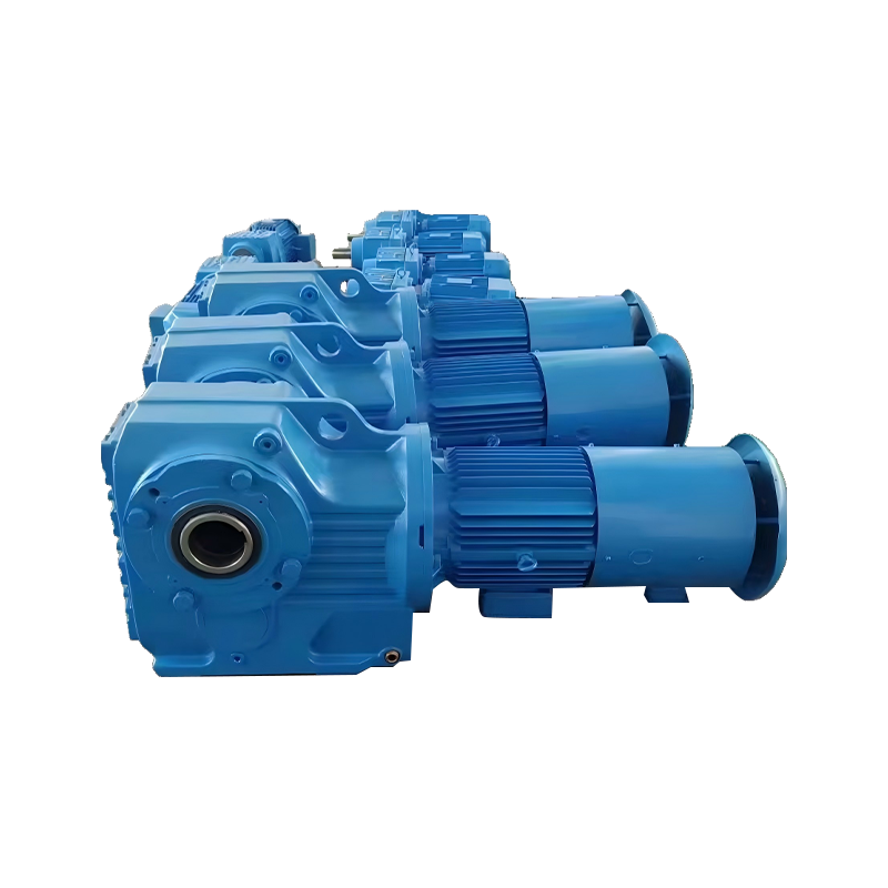 Helical Gear Reduction Motor for Cylindrical Gear Reducer DrivesIntegrated helical geared motor with high-efficiency, low-noise transmission; relevant where input shaft torque, speed, alignment, and first gear mesh reliability matter.View Product →
Power enters through the input shaft, passes into the first gear mesh, and leaves at lower speed and higher torque. The input shaft therefore sees the highest speed and often the highest rotational frequency in the reducer.
The basic relationship is straightforward: torque rises as speed falls. If a motor supplies a given power at a certain input speed, the reducer changes speed according to the gear ratio, while torque increases in proportion to the ratio, minus losses. That is why input shaft diameter, bearing selection, and lubrication matter more as input speed and duty cycle increase.
For a broader explanation of the power path, see this guide to industrial gear reducer working principles. In practice, the input shaft must remain centered under load so the first mesh does not move out of position.
Speed, torque, and shock
High-speed input shafts are sensitive to imbalance, coupling runout, and belt or brake loads. A sudden start can multiply torque well above the running value. That is why service factor and starting conditions should be checked before accepting a reducer model.
Input Shaft Dimensions, Keys, and Fits: What Buyers Must Verify
Shaft diameter, tolerance, keyway, and coupling fit are the first four items to verify before accepting a gear reducer input shaft. They are also the items most often skipped when a replacement reducer is ordered from a catalog number alone.
| Check | Why it matters | Typical field action |
|---|---|---|
| Shaft diameter and tolerance | Controls coupling fit and torque capacity | Measure at three points with a micrometer |
| Straightness and runout | Prevents vibration and bearing load spikes | Use a dial indicator near the coupling seat |
| Keyway width and depth | Prevents key shear, backlash, and fretting | Check with a keyway gauge and the matching key |
| Key material and fit | Determines shock resistance | Confirm steel grade and clearance |
| Axial location and end play | Sets bearing preload and gear position | Check shoulders, spacers, and retaining rings |
| Coupling type and fit | Affects misalignment tolerance | Verify bore, insert, and clearance |
| Seal and oil path | Prevents leakage and contamination | Inspect seal lip, drain, and breather |
| Material and heat treatment | Affects fatigue and wear life | Review material certificate and hardness |
A useful rule is to measure the actual motor shaft and the actual reducer input shaft before installation. Do not assume that a standard frame size guarantees a matching shaft. The cost of a micrometer check is far lower than the cost of an unplanned shutdown.
Matching the Input Shaft to the Motor and Driven Load
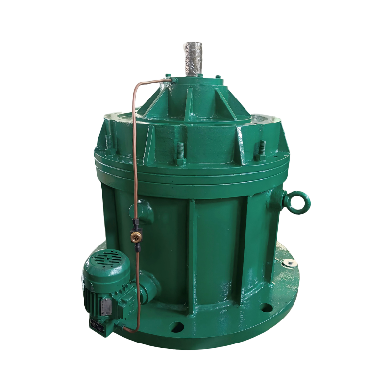 Planetary Gear Reducers for High-Precision Coaxial Drive SystemsCoaxial planetary reducers with high torque density; check input shaft fit, torque, speed, radial load, and starting conditions rather than diameter alone.View Product →
Match the input shaft to the motor and load by checking torque, speed, service factor, radial load, and starting conditions, not by shaft diameter alone. The shaft is only one part of a system that includes the motor, coupling, reducer, and driven machine.
- Confirm motor power, speed, and frame dimensions.
- Calculate required output torque and input speed from the gear ratio.
- Apply the correct service factor for the application and starting method.
- Check radial and axial loads at the input shaft, especially with belt drives or brakes.
- Review ambient temperature, dust, moisture, and lubrication method.
- Verify mounting position so oil reaches the input bearings and seal.
- Confirm coupling type, bore tolerance, key size, and axial locking method.
Service factor and starting torque
A conveyor, crusher, or crane may start under full load or with a brake that releases unevenly. In such cases, the input shaft and key must be selected for peak torque, not only running torque. If the service factor is too low, the first sign is often a loose key or a polished shaft seat.
Radial loads and overhung loads
V-belt pulleys, chain sprockets, and large couplings can create overhung loads that bend the input shaft. When these loads are high, a larger shaft or additional bearing support may be required. The reducer rating alone does not prove that the input shaft can carry a heavy side load.
Common Input Shaft Problems and Their Root Causes
Most input shaft failures come from misalignment, excessive overhung load, poor key fit, or lubrication loss, not from an undersized gear rating. The symptoms often appear before the reducer stops running, which gives maintenance teams time to correct the cause.
| Symptom | Likely cause | First inspection point |
|---|---|---|
| Vibration at high speed | Coupling runout, imbalance, or bent shaft | Dial indicator on coupling seat |
| Oil leak at input seal | Shaft wear, excessive runout, blocked breather | Seal lip and shaft surface |
| Keyway wear or fretting | Loose fit, shock load, wrong key material | Key, keyway, and coupling bore |
| Abnormal noise | Bearing damage or gear misalignment | Bearing play and tooth contact |
| Overheating | Overload, wrong oil, or excessive preload | Oil level, viscosity, and input bearing |
| Coupling slip | Undersized interference or clamp force | Coupling clamp screws and bore fit |
When a shaft problem is found, inspect the mating part before replacing only the reducer. A worn coupling bore or damaged motor shaft will repeat the same failure on the new unit.
Selection Checklist for Industrial Gear Reducers
Use a written checklist so the input shaft, reducer, and driven machine are treated as one drive train. This reduces the risk of a technically correct reducer failing because the shaft interface was wrong.
- Record motor power, full-load speed, and starting method.
- Confirm required output speed and torque.
- Select service factor based on load type, hours per day, and shock level.
- Verify input shaft diameter, key size, and coupling fit.
- Check allowable radial load at the input shaft.
- Confirm mounting position, oil fill, and cooling.
- Review environment: dust, water, temperature, and washdown.
- Ask for shaft material, hardness, and inspection report.
- Plan alignment checks after installation and after first load test.
Questions to ask the supplier
Ask for the input shaft drawing, allowable overhung load, recommended coupling, and installation tolerance. A supplier with broad industrial experience should be able to explain which shaft option fits a belt-driven, direct-coupled, or brake-mounted arrangement.
FAQ About Gear Reducer Input Shafts
These are the questions buyers ask most often when specifying or replacing a gear reducer input shaft.
What is the input shaft on a gear reducer?
It is the high-speed shaft that receives power from the motor and drives the first gear stage. It usually connects through a coupling, pulley, or brake wheel.
How do I measure an input shaft correctly?
Measure diameter at several points along the fit length, check runout with a dial indicator, and gauge the keyway width and depth. Compare the results with the reducer drawing and the motor shaft.
Can I replace only the input shaft?
Sometimes, but only after checking bearings, seals, gear contact, and housing bores. If the shaft failed from misalignment, replacing the shaft alone may not solve the root cause.
What causes keyway wear?
A loose key fit, repeated shock loads, and a coupling that is not properly supported are common causes. The key and keyway should be checked together, not separately.
How much shaft misalignment is acceptable?
The limit depends on coupling type and shaft speed. A flexible coupling accepts more misalignment than a rigid one, but even a small error can raise bearing load at high input speed. Always follow the coupling and reducer installation tolerances.
Does input shaft material matter?
Yes. Material grade, heat treatment, and surface finish affect fatigue strength, keyway wear, and seal life. For heavy-duty or high-starting-torque applications, these details should be confirmed in writing.
Final takeaway: the gear reducer input shaft is a precision interface, not a commodity detail. Confirm its dimensions, keyway, fit, alignment, and load capacity against the motor and driven machine before purchase, and inspect the mating parts after any failure. That approach keeps the reducer, coupling, and motor working as one reliable drive train.