
 English
 中文简体
Parallel Shaft Gear Reducer: Working Principle, Selection, and Duty Matching
Nov 03, 2026
A parallel shaft gear reducer is a gearbox that transmits power between two shafts lying on parallel axes, reducing motor speed and multiplying torque in the process. If a driven machine needs a ratio between roughly 1.25:1 and 200:1, efficiency above 95 percent, and a unit that can be serviced without dismantling the whole drive train, this layout is usually the most economical answer. It stops being the right answer once torque density in a confined space, or a right-angle shaft arrangement, becomes the deciding constraint.
What follows covers the geometry, the tooth-surface choices that set real load capacity, the selection checks that prevent early failure, and how the design compares with planetary and worm alternatives in ordinary industrial service.
Content
- 1 What Defines a Parallel Shaft Gear Reducer
- 2 How the Power Path Works and Where Losses Appear
- 3 Tooth Surface Options and Load Capacity
- 4 Matching the Reducer to the Real Duty
- 5 Parallel Shaft vs Planetary and Worm Layouts
- 6 Where Parallel Shaft Reducers Earn Their Keep
- 7 Installation and Maintenance That Prevent Early Failure
- 8 Frequently Asked Questions
What Defines a Parallel Shaft Gear Reducer
The defining feature is geometry rather than gear type: the input and output shafts run parallel to each other but are offset by a fixed centre distance, and each reduction stage is simply a pair of gears carried on those parallel shafts.
That arrangement produces a housing that is long and relatively low, usually split horizontally along the shaft centreline, which makes inspection and bearing replacement straightforward. Practical characteristics look like this:
- Stage ratio of about 3:1 to 8:1 per helical pair; three stages reach 200:1 and beyond.
- Helical gearing is standard above light loads because overlapping tooth contact spreads load and cuts noise; spur gearing remains common in slow, reversing duty.
- Output options include solid shafts with keys, hollow shafts with shrink discs, and flange or foot mounting.
- Input can be direct-coupled to a motor, fitted with a belt pulley, or supplied as a geared motor with the motor flanged to the housing.
- Efficiency is high and slip is effectively zero, so output speed tracks input speed accurately, which matters for metering and indexing duties.
How the Power Path Works and Where Losses Appear
Each stage converts speed into torque at a loss of roughly 1 to 2 percent, so the overall efficiency of a parallel shaft reducer is decided mainly by how many stages it contains rather than by any single manufacturing detail.
A two-stage unit typically lands around 97 percent, a three-stage unit around 95 to 96 percent. The losses split into three areas: tooth meshing, bearing friction, and oil churning. Churning is the one most often overlooked. An overfilled splash-lubricated gearbox can push sump temperature past 90 degrees Celsius even when the mechanical rating is nowhere near its limit, and the resulting oil degradation shortens bearing life long before the gears show wear.
This is why thermal capacity has to be checked alongside mechanical capacity. At high input speeds, or when the unit sits in a hot enclosure without airflow, the thermal rating may be the binding constraint rather than torque.
Tooth Surface Options and Load Capacity
Tooth hardness decides how much torque a given centre distance can carry, and it drives price more than any other single specification choice.
| Tooth surface | Typical hardness | Load capacity | Typical duty |
|---|---|---|---|
| Soft tooth surface | Below 350 HB | Moderate; larger frame for the same torque | General machinery, low shock, cost-sensitive projects |
| Medium-hard surface | Around 350 to 400 HB | Good balance of strength and running smoothness | Conveyors, mixers, fans, medium-duty continuous operation |
| Hardened and ground | 45 to 62 HRC | Highest; smaller frame for the same torque | Mills, cranes, crushers, frequent starting or reversing |
Hardened and ground teeth are not automatically the better purchase. They cost more per unit, and at low power with gentle duty the extra capacity is simply paid for and never used. The reverse mistake is more expensive: specifying a soft-tooth unit for a conveyor that starts fully loaded three times an hour usually ends in pitting within the first year.
Our hardened and medium-hard cylindrical units follow the same housing and mounting conventions, so a frame size can usually be upgraded on the same footprint if duty increases.
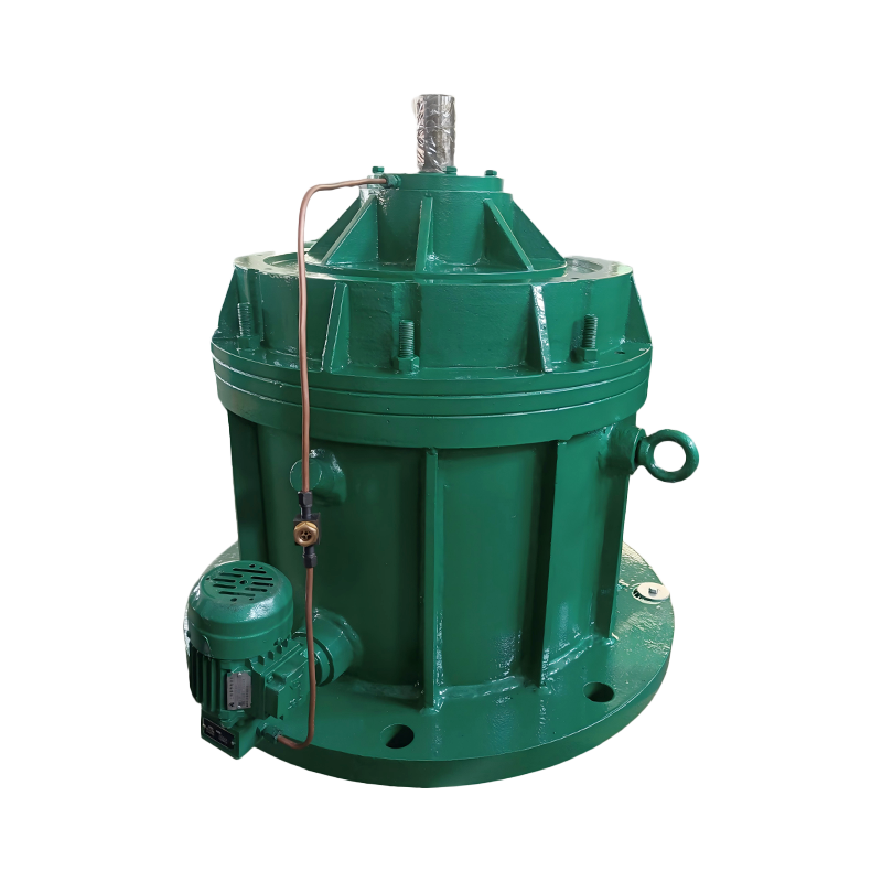
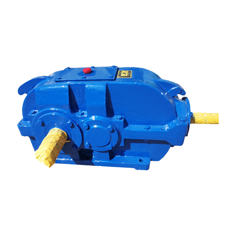 Hard-Tooth Surface Cylindrical Gear ReducerFor heavy-load industrial drives, this compact reducer offers hardened ground gearing, high load capacity and protection features for demanding operating conditions.View Product →
Matching the Reducer to the Real Duty
Selection should start from the driven machine's torque curve, not from the motor nameplate, because starting torque, breakaway torque and momentary overloads are what actually size the gearbox.
Work through these points before fixing a frame size:
- Service factor: around 1.0 for uniform loads, 1.25 for moderate shock, 1.5 or higher for heavy shock and frequent starts.
- Peak torque including starting and stall conditions, not just running torque.
- Required output speed and its tolerance; a one or two percent speed error can upset a metering or dosing process.
- Radial and axial loads applied to the output shaft by pulleys, sprockets or couplings.
- Duty cycle in hours per day, starts per hour, and whether the drive reverses.
- Ambient temperature, altitude and available cooling air around the housing.
- Mounting orientation, since oil level and breather position change with it.
- Backlash allowance if the driven equipment has positioning requirements.
- Thermal rating against the actual absorbed power at site conditions.
Units in this class are available across a wide spread of frame sizes and ratios, which makes a like-for-like swap practical when an existing drive is being re-rated.
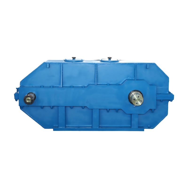 Medium-Hard Tooth Surface Cylindrical Gear ReducerA cost-effective cylindrical reducer for moderate loads, with quenched alloy-steel gearing, modular mounting and broad frame and ratio options for re-rating existing drives.View Product →
Parallel Shaft vs Planetary and Worm Layouts
Parallel shaft units win on efficiency and purchase cost at moderate ratios, planetary units win on torque density and coaxial mounting, and worm units win on ratio per stage and on holding a load without a brake.
| Layout | Efficiency | Ratio per stage | Footprint | Best fit |
|---|---|---|---|---|
| Parallel shaft | 95 to 98 percent | 3:1 to 8:1 | Long, low, offset shafts | Conveyors, mills, cranes, general continuous duty |
| Planetary | 94 to 97 percent | 3:1 to 10:1 | Compact, coaxial | Tight spaces, high torque density, mobile equipment |
| Worm | 50 to 90 percent depending on ratio | 5:1 to 100:1 | Right angle, compact | High ratios, low power, self-locking holding duty |
The efficiency gap is easy to underestimate. On a 75 kW drive running 6,000 hours a year, the difference between 96 percent and 70 percent is tens of thousands of kilowatt hours annually, which normally outweighs the price difference within a couple of years. If you want the wider picture before committing, this guide to how an industrial gear reducer works covers the fundamentals of each family.
Where the driven machine needs a 90 degree turn, a right-angle bevel-helical unit is usually preferred over adding a separate transfer gearbox, because each extra component adds cost, alignment work and another lubrication point.
Where Parallel Shaft Reducers Earn Their Keep
They show up wherever a driven machine runs continuously at moderate to high power and the drive train has room for an in-line gearbox.
- Belt and chain conveyors in mining, ports and bulk handling.
- Ball and rod mills, where high torque and steady speed matter more than compactness.
- Crane travel, hoist and long-travel mechanisms.
- Mixers, agitators and thickeners with high starting torque.
- Rolling mill auxiliaries, stacker-reclaimers and pipe piercing equipment.
- Extruders, pumps and fans in process plant.
Bulk handling is the largest single use, and it is also the duty that punishes undersized selection most visibly, because a conveyor that jams and restarts under full load applies shock torque far above its running figure.
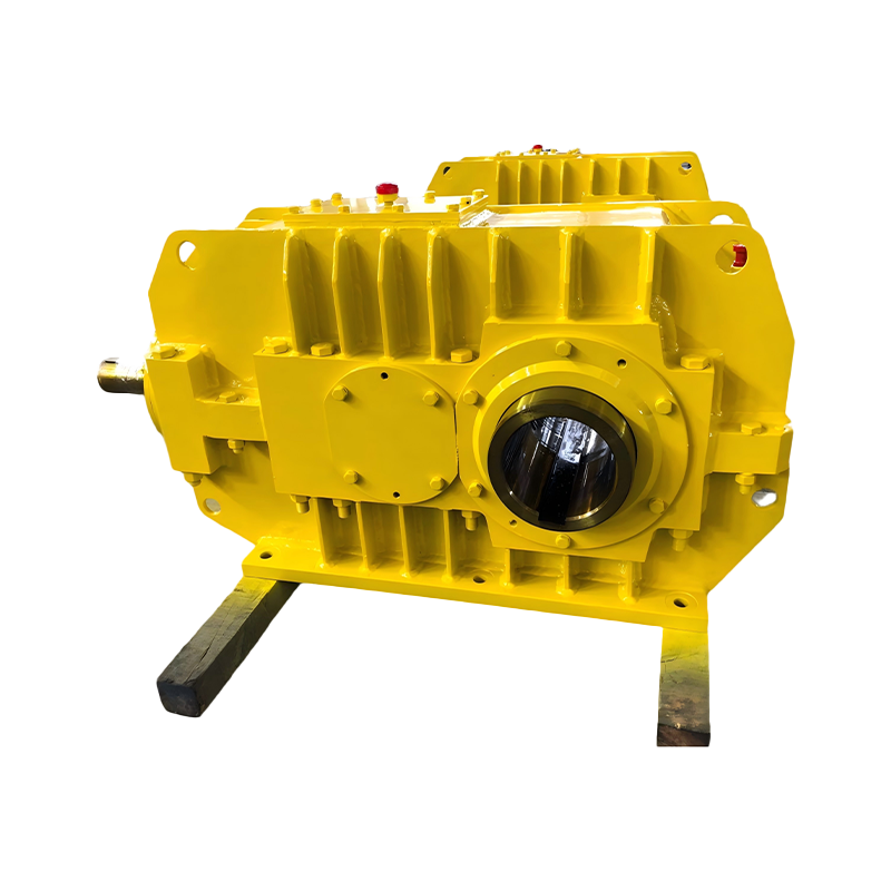 Conveyor Reducer for Belt Conveyor SystemsA rugged conveyor drive with high-torque hardened gearing, IP65 protection and optional backstop, suited to continuous bulk material handling under dust and impact.View Product →
Installation and Maintenance That Prevent Early Failure
Most premature gearbox failures trace back to alignment, lubrication or venting rather than to the gear teeth themselves.
- Check shaft alignment with a dial indicator or laser tool; a few hundredths of a millimetre of angular error is enough to load a bearing unevenly over months.
- Keep belt and chain tension within the manufacturer's limit, since over-tensioning loads the output bearing directly.
- Use the specified viscosity grade for the actual ambient temperature, and never fill above the sight glass mark.
- Drain and refill after the first 300 to 500 running hours, then follow a 5,000 to 8,000 hour interval with oil sampling at every second service.
- Confirm the breather and oil level plug are positioned for the mounting orientation; a unit rotated from horizontal to vertical without swapping them will leak or starve.
- Record noise and vibration at commissioning so later trends can be compared against a baseline.
For units in storage, fill with oil, rotate the shaft by hand monthly and keep the breather plugged until installation. A gearbox that sits outdoors for a year with an open vent will collect condensation long before it collects load.
Frequently Asked Questions
What ratio can a single-stage parallel shaft reducer achieve?
In practice 3:1 to 8:1 with helical gears. Higher single-stage ratios are possible but the pinion becomes small and the housing grows, so two stages are usually cheaper and more durable.
Can a parallel shaft reducer be mounted vertically?
Yes, but the oil level, breather and drain positions must be changed to suit the orientation. A unit set up for horizontal mounting should not be rotated without confirming the lubrication arrangement.
Are helical gears always better than spur gears?
Helical gears run quieter and carry more load per unit width because contact is gradual. Spur gears cost less, produce no axial thrust and remain a sound choice for slow, reversing or low-power duty.
Why does my gearbox run hotter than expected?
Usually overfilling, an incorrect oil viscosity, a blocked breather, sustained overload, or insufficient air movement around the housing. Check the oil level first, then the thermal rating against actual absorbed power.
Does a parallel shaft reducer hold a load without a brake?
Generally no. With helical or spur gearing the efficiency is too high for self-locking, so a holding brake or backstop is required for inclined conveyors and hoists.
A parallel shaft gear reducer is a straightforward machine that rewards careful specification more than clever installation. Get the service factor, tooth hardness and thermal rating right, keep the oil clean and the shafts aligned, and a well-chosen unit will run for a decade or more with nothing more than routine fluid changes. Start with the driven machine's torque and duty cycle, then confirm the frame size against both mechanical and thermal limits before ordering.

Contact us
-
Factory Address
No. 10, Taiyao North Road, Yaowang Town, Taixing City, Jiangsu Province, China
-
Phone
86-139 5115 9007
Copyright © TAIXING REDUCER CO., LTD. Rights Reserved.
China industrial gear reducer manufacturer Custom speed reducer supplier