 English
 中文简体
A ball mill rotating hundreds of tonnes of ore, a ladle turret swinging molten steel, a conveyor running day and night in a mine — the machine that makes these possible is not the motor alone, but the high torque gear reducer sitting between motor and load. A high torque gear reducer is a gearbox that reduces output speed while multiplying torque by a fixed ratio, so a relatively small motor can drive heavy equipment under continuous, shock, or reversing loads. When engineers ask which reducer to buy, the answer starts with three numbers: required output torque, service factor, and duty cycle. Ratio and efficiency are important, but they come after those three.
Content
What Is a High Torque Gear Reducer and How Does It Work?
A high torque gear reducer multiplies the motor's input torque by the reduction ratio, minus mechanical losses: output torque equals input torque multiplied by ratio and efficiency (Tout = Tin × i × η). For example, a motor delivering 100 Nm through a 40:1 reducer with 97% efficiency produces roughly 3,880 Nm at the output shaft while the output speed drops to one-fortieth of the input speed.
Torque capacity, however, is not set by the ratio alone. It is determined by gear tooth module and face width, the hardness of the tooth surfaces, bearing size and span, and the stiffness of the housing. Two reducers with the same ratio can have completely different torque ratings if one uses hardened and ground gears while the other uses softer, unground gears. That is why a high torque gear reducer is defined by its rated output torque rather than by the ratio printed on the nameplate.
Main Types of High Torque Gear Reducers
For heavy-duty industrial service, three designs dominate: planetary gear reducers, helical cylindrical gear reducers, and bevel-helical reducers. Worm gear reducers can also deliver high output torque, but their efficiency falls sharply as the ratio climbs, so they are rarely the best choice for continuous high-power duty.
| Type | Torque Density | Efficiency | Typical Ratio Range | Best Suited For |
|---|---|---|---|---|
| Planetary | Highest | 95–98% | 5:1 to 500:1 | Cranes, winches, compact heavy-duty drives |
| Helical cylindrical | High | 96–98% | 6.3:1 to 450:1 | Conveyors, mills, mixers, continuous duty |
| Bevel-helical | High | 94–97% | 5:1 to 400:1 | Right-angle heavy installations |
| Worm gear | Low to medium | 40–90% | 10:1 to 60:1 | Intermittent duty, low-cost compact layouts |
Planetary reducers offer the highest torque-to-volume ratio because the load is shared among several planet gears that orbit a sun gear inside a ring gear. The force is split across multiple meshes, allowing a compact unit to carry torque that would require a much larger parallel-shaft box. For a deeper look at the working principles, see this complete technical guide on planetary reducers.
Helical cylindrical reducers use parallel shafts with hardened and ground teeth. They combine high efficiency, smooth meshing, and simple maintenance, which makes them the workhorses of continuous-process industries. The cylindrical gear reducer range covers a wide choice of frame sizes for this type of duty.
Worm gear reducers use a sliding mesh between the worm and the worm wheel to achieve a high ratio in one stage, but the sliding action generates friction heat. Above roughly 30:1, efficiency can drop below 70%, so worm units are better suited to intermittent operation than to continuous high torque service.
Key Specifications to Evaluate Before Buying
Five numbers determine whether a reducer survives in your application: rated output torque, service factor, reduction ratio, thermal capacity, and backlash. A datasheet can show an impressive ratio and still hide a weak torque rating, so verify each value against your duty before ordering.
- Rated output torque (Nm) — the continuous torque the reducer can transmit safely at the specified input speed. This is the first number to compare.
- Service factor — the ratio between the catalog rating and the actual application load. It accounts for shock, starting frequency, and daily running hours.
- Reduction ratio — determined by the required output speed from a given motor speed. A 1,500 rpm motor driving a 30 rpm drum needs a 50:1 ratio.
- Thermal capacity — the maximum continuous power the reducer can dissipate as heat. High ratio and low output speed often create a thermal limit before a mechanical limit.
- Backlash — the angular play between input and output. Reversing and positioning applications require a lower backlash grade than one-direction continuous running.
The service factor is the most misunderstood number in reducer selection. The table below gives typical starting values for industrial duty classes.
| Duty Class | Typical Machines | Recommended Service Factor |
|---|---|---|
| Uniform load | Agitators, light conveyors, machine tools | 1.00–1.25 |
| Moderate shock | Belt conveyors, mixers, screw feeders | 1.25–1.50 |
| Heavy shock | Crushers, ball mills, rolling mills | 1.75–2.00 or higher |
Match the Reducer to the Application
The application determines the right gear type, frame size, and mounting arrangement more accurately than any general preference. Experience shows that matching the reducer to the real duty is what keeps maintenance costs low over a twenty-year service life.
Mining and Grinding
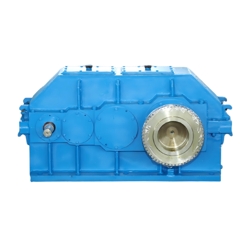
Ball mills and crushers subject the gearbox to high torque peaks and heavy shock loading. The reducer must have a massive housing, wide gears, and a service factor of 1.75 or higher. For this demanding duty, our purpose-built ball mill reducer is designed around the starting and peak torque characteristics of grinding machinery.
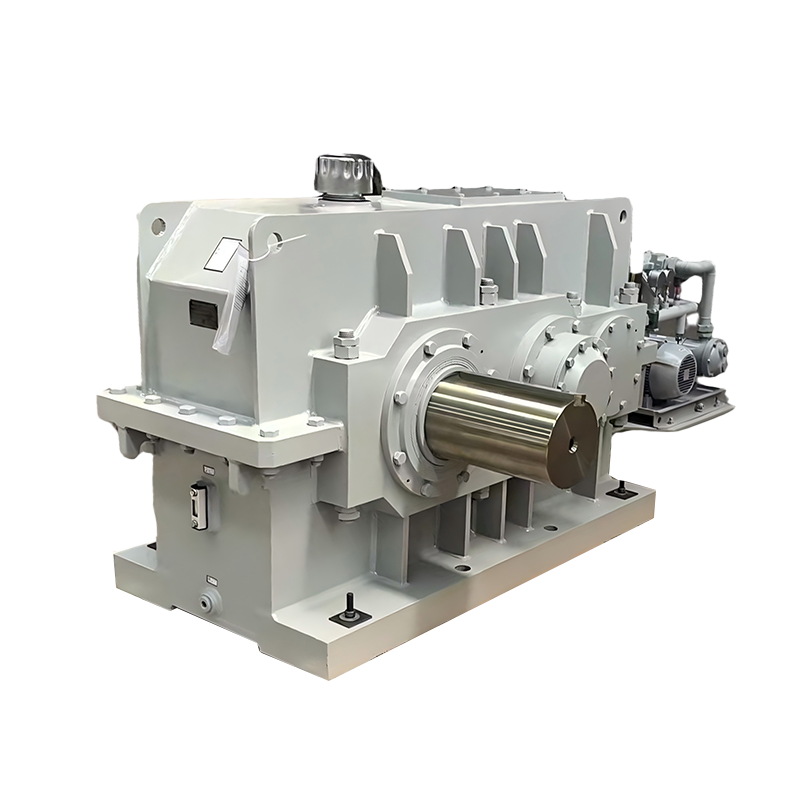 Heavy-Duty Ball Mill Reducer for Grinding MachineryThis reducer is built for ball mills and crushers, with a reinforced housing and vibration-resistant design to handle high torque peaks and continuous heavy load operation.View Product →
Cranes and Hoisting
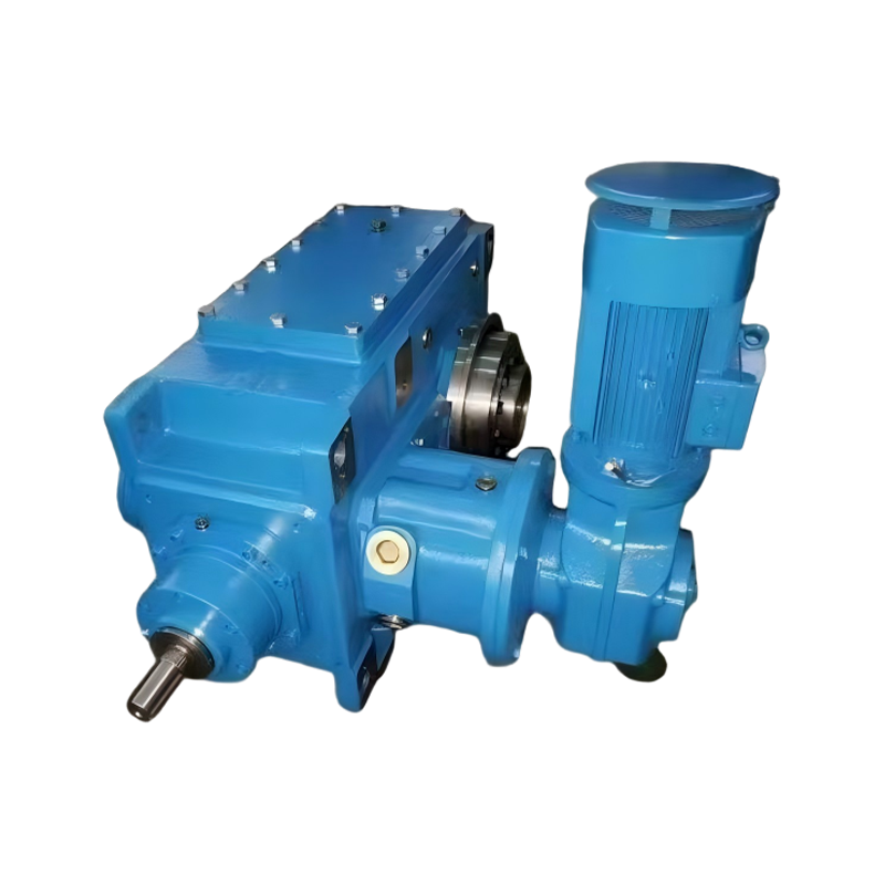
Crane travel, slewing, and hoisting motions need compact reducers with high torque density and the ability to withstand frequent starting and reversing. A planetary unit is usually the best fit because it packs the required torque into a small envelope and can mount directly beside the drum. Our planetary gear reducer series is built for these repetitive heavy-duty cycles.
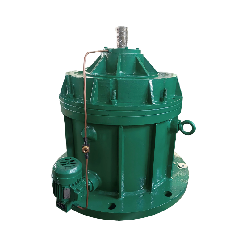 Compact Planetary Gear Reducer with High Torque DensityDesigned for crane travel, slewing, and hoisting motions, this planetary unit offers compact installation and durability for frequent starting and reversing in heavy-duty cycles.View Product →
Conveyors and Bulk Handling
Long conveyors and stacker-reclaimers run continuously for years, so efficiency, oil temperature, and serviceability matter as much as torque. A modular heavy-duty gearbox delivers the required torque and ratio in a flexible frame arrangement and is easier to maintain in the field. Our modular heavy-duty gearbox is one option within the wider conveyor reducer family.
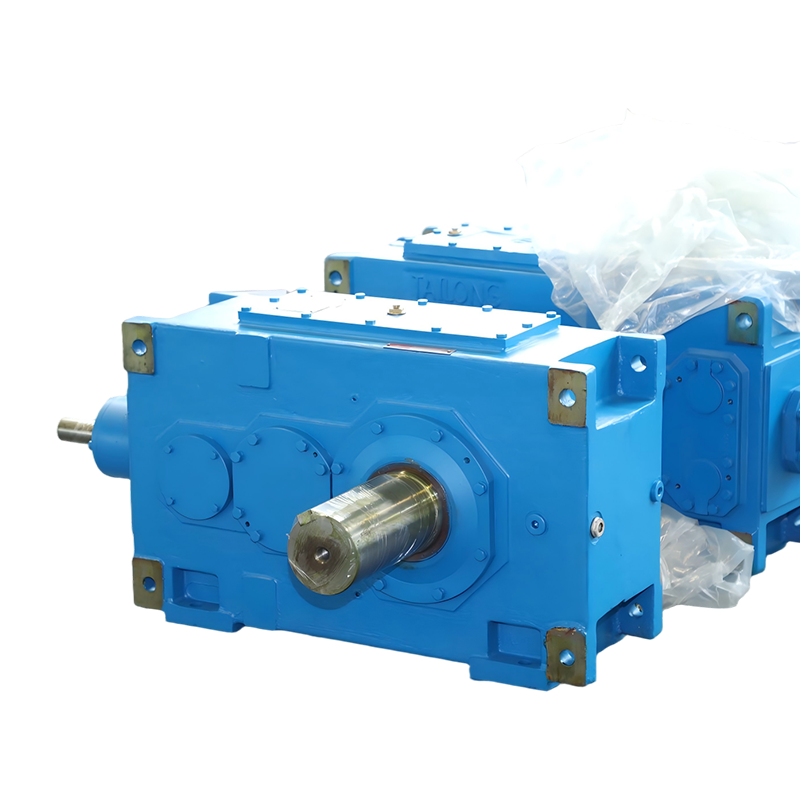 Modular Heavy-Duty Gearbox for Conveyor ApplicationsThis gearbox supports long-running conveyors with modular flexibility, high efficiency, and easy serviceability, making it a practical choice for continuous material handling systems.View Product →
Manufacturing capability becomes critical when the reducer is large or non-standard. Our plant has produced reducers since 1984, covering sixteen series and more than ten thousand specifications, with in-house equipment that includes 3-metre gear grinders and 3.2-metre gear hobbing machines. This allows one-piece machining of large housings and gears, which keeps accuracy and concentricity under control for high torque custom orders.
Common Procurement Mistakes and How to Avoid Them
Most premature gear failures can be traced to a small set of correctable mistakes: undersizing the torque, ignoring the thermal rating, confusing peak torque with rated torque, and choosing the gear type before defining the application.
- Undersizing the torque — Always use the actual running load plus starting torque, not the motor nameplate alone. A drive motor can deliver much more torque during start-up than its nominal rating.
- Ignoring the thermal limit — A reducer can be mechanically rated for a torque it cannot dissipate as heat during long running hours. For continuous duty, compare the thermal power rating with the absorbed power.
- Confusing peak torque with rated torque — Peak torque is an occasional overload capability, not a continuous rating. Running near the peak rating for long periods damages bearings and gear teeth.
- Selecting the gear type too early — A worm reducer may look attractive at first cost, but in continuous operation its lower efficiency produces energy bills that quickly exceed the initial saving.
- Forgetting lubrication and cooling conditions — High torque generates heat, especially at low output speeds. Check oil volume, cooling fan, and whether auxiliary cooling is required for your duty cycle.
Frequently Asked Questions
The answers below cover the questions that most often decide a high torque gear reducer purchase.
Which type of gear reducer provides the highest torque?
Planetary gear reducers provide the highest torque for a given physical size because multiple planet gears share the load simultaneously. For a fixed footprint, no other common type matches the torque density of a planetary stage.
What does the service factor mean in a reducer datasheet?
The service factor is the catalog torque rating divided by the actual application torque. A reducer with a 1.5 service factor can handle 50% more than its continuous nominal torque under normal operating conditions, which gives a safety margin for shocks and load variations.
Can a worm gear reducer deliver high torque?
Yes, a worm gear reducer can deliver high torque at the output, but at the cost of efficiency and heat. At high ratios its efficiency can drop to 40–70%, so it is best suited to intermittent duty rather than continuous high-power service.
How do I calculate the output torque I need?
Use the formula T = (P × 9,550) / n, where T is torque in newton-metres, P is power in kilowatts, and n is the required output speed in revolutions per minute. Add the service factor margin and the inertia of the driven equipment to that base figure.
Is hardened and ground gear quality necessary for high torque?
Yes, for continuous heavy-duty service. Hardened and ground tooth surfaces resist pitting and wear, while a smaller tooth module with more teeth in mesh gives smoother load distribution. Soft-tooth designs are cheaper but wear out faster under sustained high torque.