 English
 中文简体
An agitator gear reducer is the speed-reducing transmission between the drive motor and the agitator shaft. It converts high motor speed into the low, high-torque rotation that mixing, blending, and reaction processes require. A typical 45 kW motor running at 1,450 rpm produces about 300 N·m of torque; driving an agitator at 45 rpm requires about 9.5 kN·m of output torque — over thirty times the motor shaft torque — and the reducer must supply that continuously while carrying the weight of the shaft, impeller, and process loads.
The practical reality is that two reducers with the same ratio can have very different longevity on the same agitator. Service factor, mounting style, overhung load capacity, and thermal rating determine whether a unit runs for twenty years or fails within two. This guide explains how an agitator gear reducer works, compares the four main types, and walks through the sizing, mounting, and maintenance decisions that matter in a plant.
Content
How an Agitator Gear Reducer Works
An agitator gear reducer works by reducing input speed through one or more meshing gear stages and multiplying torque by the inverse of the ratio, minus mechanical losses. For a three-stage helical unit with a 25:1 ratio and 97% efficiency per stage, the total efficiency is about 91%, so the output torque is approximately 23 times the input torque. A standard four-pole motor runs at about 1,450 rpm, so a 25:1 reducer delivers roughly 58 rpm to the impeller — a typical speed for blending and suspension mixing.
The same principles of tooth contact, bearing support, and housing rigidity apply across all heavy-duty drives used in mixing lines. If you are new to gearbox internals, our review of how an industrial gear reducer works explains the differences between helical, bevel, and planetary stages in more detail.
Main Types of Gear Reducers for Agitators
Four gearbox architectures dominate agitator service: helical, bevel-helical, planetary, and worm reducers, each with a different trade-off between efficiency, torque density, and first cost.
Helical Gear Reducers
Helical gear reducers are the default choice for top-entry agitators. They deliver 96–98% efficiency per stage, run quietly, and cover ratios from about 5:1 to 500:1 in two or three stages. Most mixing duties with low-to-medium viscosity liquids — blending, dissolving, and heat-transfer circulation — are well served by a helical gear reduction motor mounted inline with the impeller shaft.
 Helical Gear Reduction Motor for Top-Entry AgitatorsThis integrated helical gear motor offers over 95% efficiency, low noise, and modular layouts. It suits low-to-medium viscosity mixing duties in top-entry installations, balancing economy and reliable performance.View Product →
Planetary Gear Reducers
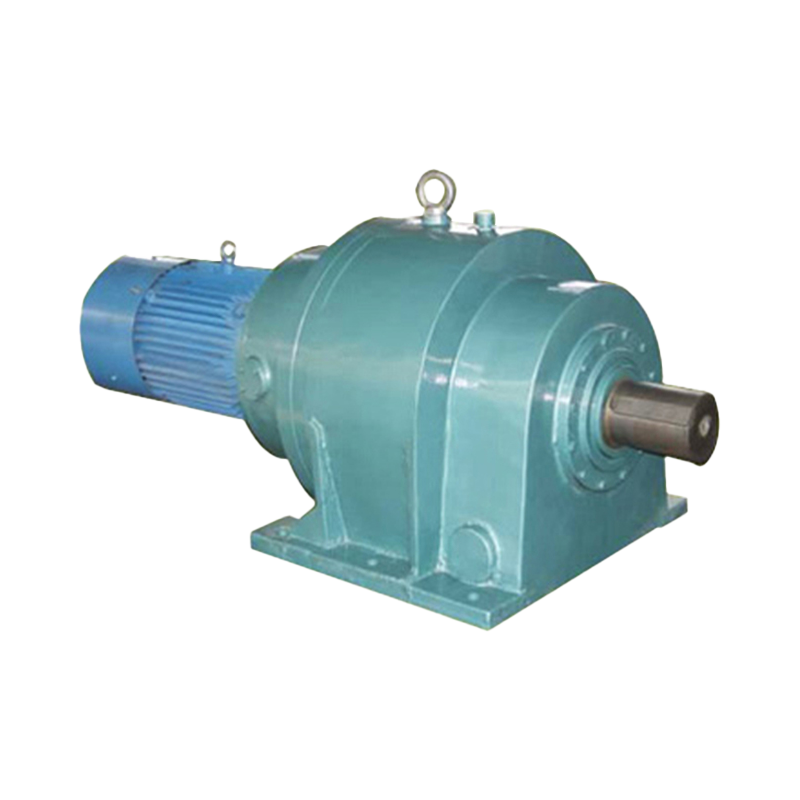
Planetary gear reducers put the same torque in a much smaller envelope by dividing the load among several planet gears orbiting a sun gear. Efficiency is 95–98%, and torque density is the highest of any common design. That matters when the agitator is mounted on a vessel top with limited headroom or when a large reactor requires very high torque at 20–60 rpm.
 Planetary Gear Reducers for High-Torque Agitator DrivesWith compact coaxial design and single-stage efficiency above 97%, these reducers deliver high torque density. They are ideal when headroom is limited or large reactors require strong torque at low speeds.View Product →
Bevel-Helical Gear Reducers
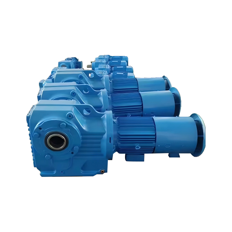
Bevel-helical reducers introduce a right-angle bevel stage, allowing the motor to sit horizontally while the agitator shaft runs vertically. This layout flexibility helps in low-clearance plants, but the bevel stage reduces total efficiency slightly to about 94–96%.
Worm Gear Reducers
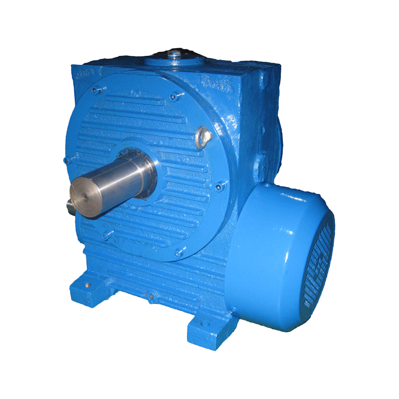
Worm gear reducers are the least expensive option and work acceptably on small portable mixers and intermittent duties. Their sliding gear contact drops efficiency to 50–90% depending on ratio; above 40:1, a worm unit can waste more than a quarter of the input power as heat. For continuous large-scale agitation, the ongoing electricity cost quickly exceeds the initial price saving.
| Type | Ratio range | Efficiency | Torque density | Typical agitator duty |
|---|---|---|---|---|
| Helical | 5:1–500:1 | 96–98% per stage | Medium-high | Top-entry mixers, blending, low- to medium-viscosity service |
| Bevel-helical | 10:1–300:1 | 94–96% total | High | Right-angle top entry, restricted headroom |
| Planetary | 15:1–500:1 | 95–98% | Very high | Compact top entry, reactors, high-torque kneaders |
| Worm | 7.5:1–100:1 | 50–90% | Low | Portable mixers, intermittent duty |
For a plant running 24/7, the difference between 90% and 95% efficiency on a 30 kW mixer is about 1.7 kW of extra heat — roughly 13,600 kWh per year that must be rejected through the housing or an auxiliary cooling system.
How to Size an Agitator Gear Reducer
Sizing an agitator gear reducer starts with the required output torque, not with the motor nameplate, because the same 22 kW motor can correspond to very different shaft loads at different speeds.
- Determine the impeller power demand from the process design. For turbulent mixing, P = Np × ρ × n3 × D5, where Np is the impeller power number (typically 0.3 to 6.0), ρ the fluid density, n the rotational speed, and D the impeller diameter.
- Define the output speed from the mixing requirement — slow blending at 20–60 rpm, medium mixing at 60–120 rpm, or high-speed dissolving above 150 rpm.
- Calculate the nominal output torque: T (N·m) = 9,550 × P (kW) / n (rpm).
- Apply the service factor: Tdesign = T × SF.
- Check the overhung load and axial thrust capacity against the actual impeller weight, fluid drag, and drive arrangement.
- Verify the thermal rating for the ambient temperature and duty cycle.
Agitators are not uniform loads. The impeller sees changing fluid viscosity, solids settling, and start-up through settled material, so the reducer must be selected against an application service factor rather than the motor rating alone.
| Duty class | Load characteristics | Service factor |
|---|---|---|
| Uniform | Low-viscosity liquids, blending, heat-transfer circulation | 1.25 |
| Moderate | Suspensions, dissolving, slurries up to 10% solids | 1.50 |
| Heavy | High-viscosity pastes, batch reactors with solids, 24-hour continuous operation | 1.75–2.00 |
Selecting a reducer rated exactly at the motor power is the most common mistake. The service factor is what protects the gearbox from torque spikes during impeller start-up and from continuous overload when viscosity rises.
Mounting Styles and Installation Considerations
Mounting style determines how the agitator shaft loads are transmitted into the reducer housing, and it must be settled before any other mechanical detail because the flange, shaft, and bearing arrangement all depend on it.
- Top-entry mounted: The reducer flanges to a vessel nozzle and the impeller shaft is inserted into a hollow output shaft locked with a shrink disc or key. This arrangement carries the full weight and axial thrust of the agitator.
- Side-entry mounted: The reducer is foot-mounted on a support pedestal beside the tank, usually with a universal joint or coupling. It needs a torque arm and careful alignment to avoid bending the output shaft.
- Direct coupled: A motor and reducer assembly sits directly above the agitator; this is the most compact design and gives the best concentricity.
- Belt driven: A belt between the reducer output and the agitator shaft adds design flexibility but also increases the overhung load on the reducer's low-speed shaft, which must be checked separately.
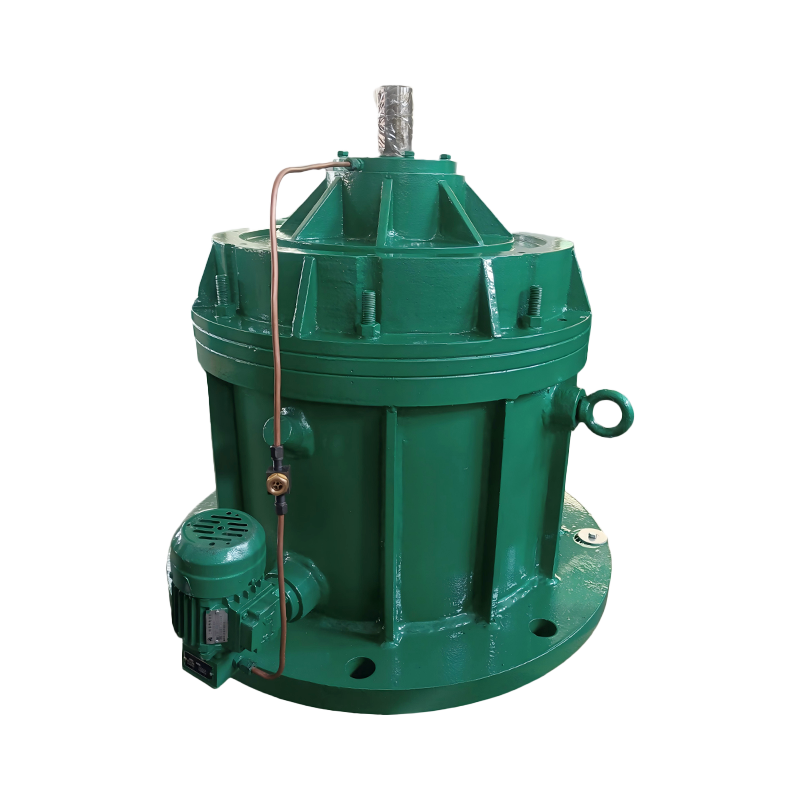
For very large agitators or non-standard vessel layouts, a modular heavy-duty gearbox with a custom flange, shaft extension, and sealing arrangement handles the combined radial and axial loads more reliably than a standard catalogue unit. Compare the required overhung load against the reducer's rated value; this check is at least as important as the torque rating.
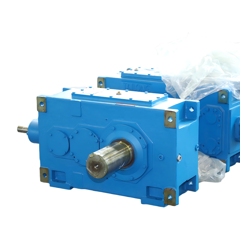 Modular Heavy-Duty Gearbox for Non-Standard Agitator LayoutsThis gearbox combines standardized modules with reinforced load capacity and IP65+ sealing, handling combined radial and axial loads reliably. It suits continuous heavy-duty mixing applications with custom flange and shaft needs.View Product →
Efficiency and Operating Cost
Efficiency differences between reducer types are small per stage, but they compound into significant operating costs in continuous service.
Consider a 30 kW output requirement running 8,000 hours per year. At 95% reducer efficiency, the input power is 31.6 kW; at 90%, it is 33.3 kW. The extra 1.7 kW of losses costs about $1,100 per year at $0.08/kWh, and over a ten-year life the higher-efficiency reducer saves more than $10,000 on a single mixer line. A more efficient gearbox also runs cooler, which extends oil and seal life and reduces the need for fans or oil coolers.
Common Failure Modes and Maintenance
Most agitator reducer failures trace back to three causes: incorrect oil, sustained overload above the service factor, and shaft misalignment or impeller imbalance. Each symptom usually has a findable root cause before serious damage occurs:
- Overheating: wrong oil viscosity, overfilled oil level, obstructed cooling fins, plugged breather, or continuous overload.
- Oil leakage: worn shaft seal, overfill, a plugged breather that pressurizes the housing, or condensate contamination.
- Excessive noise: bearing wear, gear tooth pitting, or structural resonance excited by the impeller speed.
- Vibration: coupling misalignment, loose foundation bolts, or an unbalanced impeller.
Maintenance follows a simple schedule. Change the oil after the first 200–300 running hours to flush assembly debris, then every 2,500–5,000 hours or annually, whichever comes first. Check the oil level weekly with the unit stopped, verify that the breather is clean, and inspect for leaks at the low-speed shaft seal. Oil analysis every six months catches bearing and gear wear early. The oil specification matters more than the brand: most helical and planetary agitator reducers use ISO VG 220 or VG 320 mineral oil for ambient temperatures between about −10 °C and 40 °C. In hot, dusty, or chemically aggressive atmospheres, switch to a synthetic PAO oil and halve the change interval.
Frequently Asked Questions About Agitator Gear Reducers
What size gear reducer do I need for an agitator?
Start from the process power requirement. If the impeller needs 30 kW at 50 rpm, the gearbox must deliver at least 9,550 × 30 / 50 = 5,730 N·m continuously. Multiply by the service factor — 1.5 for suspension duty gives about 8,600 N·m — and choose a reducer whose rated torque at the selected ratio meets or exceeds that value.
Can I use a worm gear reducer for an agitator?
Yes, but only for light, intermittent mixing. Worm reducers are compact and inexpensive, but efficiency falls below 80% at ratios above 30:1, so the motor draws more current and the gearbox runs hot. For continuous operation, a helical or planetary reducer pays for itself through electricity savings alone.
What is the difference between a gearmotor and a gear reducer for agitator duty?
A gearmotor integrates the motor and gearbox into one factory-aligned assembly, saving space and ensuring accurate concentricity. A separate gear reducer is coupled to a bare-shaft motor through a flexible coupling or belt, which allows easier motor exchange and speed changes but requires precise alignment during installation.
Why does my agitator reducer overheat?
The usual causes are wrong oil viscosity, an overfilled oil level, clogged cooling fins or breather, and running continuously above the selected service factor. Stop the unit, check the oil level, confirm the viscosity grade, and compare the actual motor current with the nameplate rating.
How often should I change the oil in an agitator gearbox?
Change it after the first 200–300 running hours, then every 2,500–5,000 hours or once a year, whichever comes first. Reduce the interval by half in dusty or chemically aggressive areas and use oil analysis to set the final schedule.