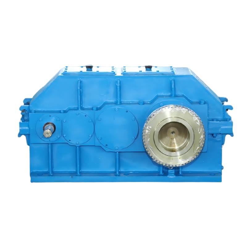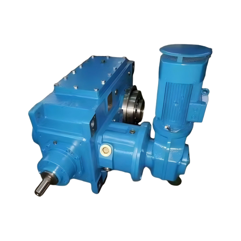
 English
 中文简体
中文简体Choosing a gear reducer starts with a load number, not a catalog page. The load number is the output torque your driven machine requires, multiplied by a service factor that accounts for shock and duty. Once that torque is known, the rest of the selection flow follows a logical order: calculate the ratio from motor speed and output speed, choose a gear family that fits the torque and application, verify the mounting and shaft configuration, then confirm efficiency and thermal rating.
Content
- 1 What Is a Gear Reducer and Why Does Choice Matter?
- 2 Key Parameters for Gear Reducer Selection
- 3 Gear Reducer Types and Recommended Applications
- 4 Gear Reducer Comparison Table
- 5 Step-by-Step Reducer Selection Process
- 6 Mounting and Shaft Configuration
- 7 Application-Specific Selection Advice
- 8 Frequently Asked Questions
What Is a Gear Reducer and Why Does Choice Matter?
A gear reducer is a mechanical unit that reduces input speed and increases output torque through meshing gears. If a 1,450 rpm motor drives a conveyor pulley that must turn at 36 rpm, a 40:1 reducer makes that possible while multiplying torque by roughly the same factor, minus efficiency losses. The concept is simple, but the choices are not: gear type, tooth hardness, housing, lubrication, and mounting all affect real-world performance.
To understand the internal geometries and operating principles before specifying, it helps to review how an industrial gear reducer works and which type suits which task. That background matters because two reducers with the same ratio can have very different efficiency, noise, and shock-load tolerance.
Key Parameters for Gear Reducer Selection
Required output torque is the starting point for any reducer selection. The practical selection process checks five parameters, in this order: torque, ratio, efficiency, duty cycle, and thermal rating.
Output Torque and Service Factor
Calculate load torque from the machine's resistance at the output shaft, which for a conveyor means belt tension and friction, for a mixer fluid resistance, and for a crane the lifted load and acceleration. Multiply by the service factor to account for shock loading, starts per hour, and daily operating time. A steady fan may need a service factor of 1.0 to 1.25; a rolling mill or crusher may need 2.0 or higher. Choose a reducer whose catalog rating equals or exceeds this adjusted torque.
Reduction Ratio
The ratio is the motor speed divided by the desired output speed. If the motor runs at 1,470 rpm and the output must be 30 rpm, the ratio is 49. Standard ratios such as 40, 50, or 63 are common; select the nearest standard ratio and verify that the resulting output speed remains within your process tolerance. For machines that need a specific surface speed or feed rate, even a one-tooth difference on a small pinion changes the ratio noticeably.
Efficiency
Efficiency determines how much input power becomes useful output power and how much becomes heat. Helical and planetary reducers typically reach 95% to 98% per stage, while worm reducers range from about 50% to 90%, with the lowest efficiency at high ratios and low input speeds. In intermittent duty, lower efficiency is rarely a problem; in continuous operation, heat buildup can shorten lubricant life and damage seals, so the thermal power rating must be checked alongside the mechanical rating.
Duty Cycle and Ambient Conditions
Operating hours per day, starts per hour, ambient temperature, dust, and humidity all affect the reducer's required thermal rating and protection level. An IP65 enclosure, forced lubrication, or an external cooling fan may be necessary in hot or dusty plants. Confirm that the selected unit's thermal capacity exceeds the applied power at your specific duty cycle.
Gear Reducer Types and Recommended Applications
Every gear reducer family trades off efficiency, torque density, cost, and geometry differently, so the right type follows from the application, not from habit. The five most common families are helical, planetary, worm, bevel, and cycloidal.
Helical (Cylindrical) Gear Reducers
Helical reducers use parallel shafts and angled teeth that engage progressively, which gives quiet operation, high efficiency, and good load sharing. They are the default choice for conveyors, mixers, cranes, hoists, and general machinery. For heavy loads, ground hardened gears improve load capacity and service life; our hardened tooth surface cylindrical gear reducer is built for continuous, high-torque service. For the complete set of parallel-shaft options, see our gear reducer product range.
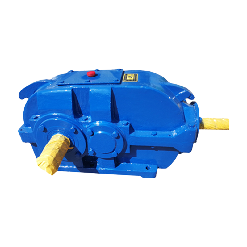 Hard-Tooth Surface Cylindrical Gear Reducer Manufacturer, FactoryTaixing Reducer is a China Hard-Tooth Surface Cylindrical Gear Reducer manufacturer & factory, with years of experience in industrial spe...View Product →
Planetary Gear Reducers
Planetary reducers concentrate torque in a compact coaxial package, because the sun gear, planet gears, and ring gear share the load across multiple meshes. This design gives the highest torque density of any common reducer type, making it a strong candidate for servo-driven machinery, rotary tables, mobile equipment, and any application where space is limited. A planetary gear reducer with hardened and ground gears offers high precision, low backlash, and long life under reversing loads.
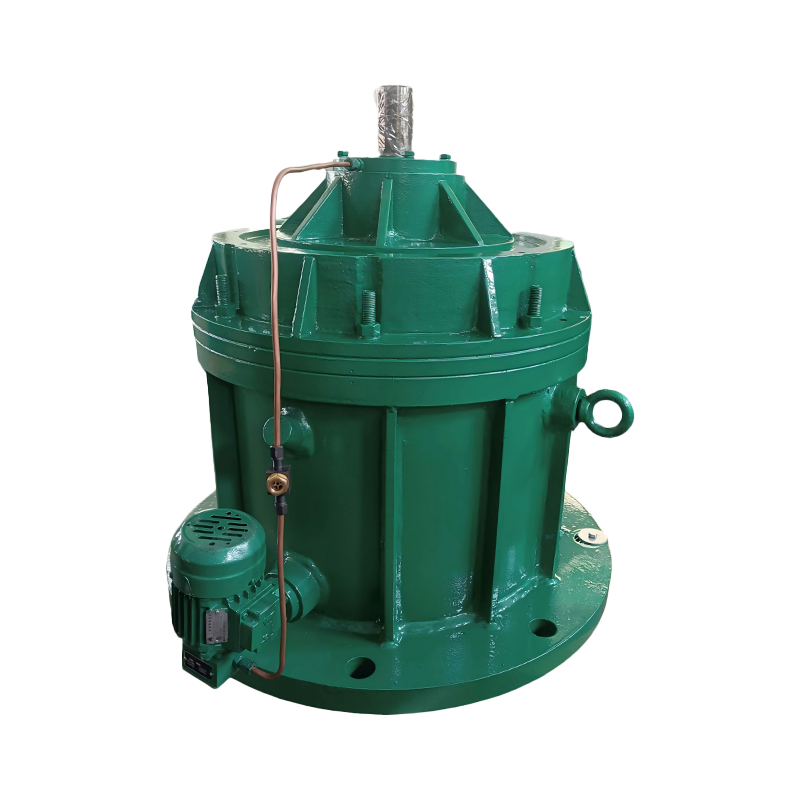 Planetary Gear Reducers Manufacturer, FactoryTaixing Reducer is a China Planetary Gear Reducers manufacturer & factory, with years of experience in industrial speed reducer. Wholesal...View Product →
Worm Gear Reducers
Worm reducers provide right-angle power transmission in a compact, low-cost package and handle high reduction ratios in a single stage almost silently. The sliding contact between worm and wheel, however, limits efficiency and generates heat, so these units suit intermittent duty and moderate power best. When the application demands more load capacity than a standard single-enveloping unit can deliver, a double-enveloping worm gear reducer provides greater contact area and torque.
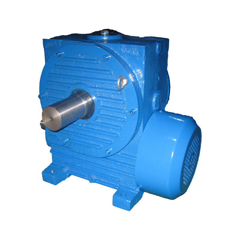 Double-Enveloping Worm Gear Reducer Manufacturer, FactoryTaixing Reducer is a China Double-Enveloping Worm Gear Reducer manufacturer & factory, with years of experience in industrial speed reduc...View Product →
Bevel Gear Reducers
Bevel reducers change the direction of power by 90 degrees with straight, spiral, or hypoid teeth. Spiral and hypoid bevels run quieter and carry more load than straight bevels, making them common in right-angle conveyor drives, pump drives, and machine tools where efficiency and positional accuracy matter.
Cycloidal Reducers
Cycloidal reducers use an eccentric cam and a set of cycloidal discs instead of conventional gear teeth. They withstand high shock loads, offer high reduction in a compact body, and tolerate brief overloads well, which is why they excel in robotics, indexing tables, and heavy-impact applications.
Gear Reducer Comparison Table
The table below summarizes the key trade-offs across the five reducer families.
| Type | Efficiency | Single-Stage Ratio | Torque Density | Best Application |
|---|---|---|---|---|
| Helical | 96-98% | 3:1 to 10:1 | Medium | Conveyors, mixers, cranes |
| Planetary | 95-98% | 3:1 to 12:1 | High | Servo and indexing drives |
| Worm | 50-90% | 5:1 to 60:1 | Low | Right-angle intermittent duty |
| Bevel | 95-98% | 1:1 to 5:1 | Medium | Right-angle high-speed drives |
| Cycloidal | 90-95% | 6:1 to 87:1 | High | Shock loads, robotics |
Efficiency values are approximate and depend on ratio, load, lubricant, and manufacturer tolerance.
Step-by-Step Reducer Selection Process
The selection process reduces to eight verifiable steps, so nothing is left to guesswork.
- Determine the motor input speed in rpm and the required output speed of the driven machine.
- Calculate the reduction ratio: R = input speed divided by output speed.
- Determine the load torque at the output shaft from the machine's resistance and inertia.
- Multiply the load torque by the service factor for the duty class to obtain the required rated torque.
- Select a reducer family based on torque, efficiency, shock loading, and axis orientation.
- Verify the catalog rating at the chosen ratio meets or exceeds the required rated torque.
- Check the thermal rating for continuous operation, especially for worm reducers.
- Confirm mounting position, shaft sizes, and coupling compatibility.
Mounting and Shaft Configuration
The geometric envelope is as important as the torque rating. Reducers are built with parallel shafts, right-angle shafts, or coaxial shafts, and each layout suits different machine arrangements.
Parallel-shaft units suit installations where the motor and machine sit side by side. Right-angle worm or bevel units fit where the motor must be mounted around a corner. Coaxial planetary units keep the motor, reducer, and machine in one straight line, which saves floor space and simplifies alignment.
Mounting styles include foot-mounted, flange-mounted, and shaft-mounted designs. Foot-mounted reducers bolt to a foundation or frame and are easiest to align and service. Flange-mounted units bolt directly to the machine housing, saving space and eliminating alignment issues. Shaft-mounted reducers install directly on the driven shaft, often with a torque arm, which simplifies retrofits but requires careful reaction-arm design.
Application-Specific Selection Advice
Different industries place different demands on a reducer, so the same torque rating is not automatically the same product.
In mining and bulk handling, shock loads and dust dominate, so a hardened helical or planetary unit with a generous service factor and good sealing is essential. In crane and hoist duty, the reducer must handle frequent starts, braking, and occasional overloads, requiring a robust case and high thermal capacity. In mixing and agitation, low-speed high-torque output with a large-diameter shaft is typical, and the reducer must also support significant axial thrust.
Buying from a manufacturer with a broad product spectrum lets you match the exact gearbox architecture to the application rather than forcing a generic unit to fit. Suppliers who produce cylindrical gear reducers, planetary reducers, and worm reducers under one roof can also advise on cross-type trade-offs during selection. To see how the wider product portfolio maps to industrial duty, you can visit our gear reducer product range.
Frequently Asked Questions
What is the most important factor when choosing a gear reducer?
Output torque, adjusted for service factor, is the most important number. If the reducer cannot deliver the required torque at the rated speed, nothing else matters. After torque, check the reduction ratio, efficiency, and mounting.
How do I calculate the gear ratio I need?
Divide the motor input speed by the desired output speed. For example, 1,450 rpm input and 36 rpm output gives a 40.3:1 ratio. Select the nearest standard ratio and verify the resulting speed within your tolerance band.
Should I use a worm or helical gear reducer?
Use a helical reducer whenever you need high efficiency, continuous operation, or a parallel-shaft layout. Use a worm reducer when you need right-angle transmission, a compact footprint, or very high single-stage reduction, and the duty is intermittent rather than continuous.
What service factor should I choose?
Light, steady loads with up to eight hours of daily operation typically use a 1.0 to 1.25 service factor. Moderate shock loads use 1.25 to 1.75. Heavy shock or reciprocating loads use 1.75 to 2.5 or higher. Always verify the manufacturer's duty classification table.
Can I oversize a gear reducer to be safe?
Moderate oversizing is acceptable, but excessive oversizing reduces efficiency, increases cost and weight, and can introduce misalignment issues with couplings. Select the smallest unit whose torque, thermal, and service ratings satisfy the application.
Choosing a gear reducer is a process of eliminating options, not accumulating them. Define the torque, calculate the ratio, choose the gear architecture, verify the mounting, and confirm the thermal rating. A reducer selected this way will run quietly, stay within temperature limits, and deliver years of trouble-free service, which is what a gear reducer is ultimately for.