 English
 中文简体
Gear reducer calculators are practical tools for anyone involved in reducer selection, from plant engineers to equipment buyers. The essential insight is that ratio, speed, and torque are tightly linked: a higher reduction ratio lowers output speed but increases output torque, while motor power remains roughly constant. The right calculator gives you the ratio you need, but it cannot tell you which reducer will survive your actual load profile. A good selection combines the calculated ratio with a realistic service factor and efficiency check. This guide shows how to use a gear reducer calculator, explains the formulas behind it, and highlights the selection details that matter most.
Content
- 1 Why Gear Reducer Calculator Accuracy Matters
- 2 Gear Reducer Calculator Formulas You Need
- 3 How to Use a Gear Reducer Calculator Step by Step
- 4 Worked Example: Conveyor Drive Reducer Calculation
- 5 Major Reducer Types and How They Affect Calculator Results
- 6 Key Selection Factors Beyond the Calculator
- 7 FAQ
- 8 Final Insights
Why Gear Reducer Calculator Accuracy Matters
Accurate calculation prevents costly mistakes such as undersized output shafts, overspeed components, or torque overload. In industrial applications, a reducer that is slightly too small may run for a while but will fail prematurely under shock loads. A reducer that is too large wastes energy, increases cost, and may cause high backdrive torque on the driven equipment. A gear reducer calculator reduces this uncertainty by converting your known input speed and torque demand into concrete ratio and capacity requirements. For multi-stage and planetary reducers, the calculator becomes even more important because you need to distribute the reduction across stages and account for efficiency losses at each mesh. A simplified approach that ignores efficiency often leads to a 2–5% torque shortfall, which on a high-output-torque machine can be the difference between years of service and a shaft failure. So, treat the calculated values as a starting point, not a final guarantee.
Gear Reducer Calculator Formulas You Need
The core formulas are reduction ratio, output speed, output torque, and service factor. Once you know the input motor speed and the required output speed, the remaining values follow directly from the ratio. Efficiency is the only parameter that introduces a multiplier; it accounts for friction losses at each gear mesh. Use the values below for a preliminary calculation, but always confirm the final numbers with the reducer manufacturer's catalogue.
| Parameter | Formula | Example | Unit |
|---|---|---|---|
| Reduction ratio (i) | i = input speed / output speed | 1470 rpm / 60 rpm = 24.5 | ratio |
| Output speed | n_out = n_in / i | 1470 / 24.5 = 60 | rpm |
| Output torque | T_out = T_in × i × η | 58.9 Nm × 24.5 × 0.95 = 1370 Nm | Nm |
| Service factor | K = rated torque / actual output torque | 2100 Nm / 1400 Nm = 1.5 | dimensionless |
How to Use a Gear Reducer Calculator Step by Step
Start with the required output speed, derive the ratio, then verify torque and service factor before ordering. The process below creates a clean audit trail, which also helps when you need to compare offers from different suppliers.
- Define the input motor speed. Use the nameplate value; most 50 Hz motors are 1450 rpm or 2970 rpm, but your motor may differ.
- Determine the required output speed from the driven machine. A conveyor may need 60 rpm; a ball mill may need 16 rpm.
- Calculate the required reduction ratio with i = n_in / n_out.
- Select the nearest standard ratio from the manufacturer's catalogue. Standard ratios commonly include 7.5, 10, 12.5, 15, 20, 25, 31.5, 40, 50, 63, 80, 100, 125, and 160.
- Recalculate the actual output speed after choosing the standard ratio.
- Compute the required output torque from the load and compare it with the reducer's rated torque.
- Apply the service factor based on the driven machine class, operating hours, and starting frequency.
- Check thermal capacity, mounting position, and shaft loads. These are not calculated by a simple gear ratio calculator but are essential for a reliable installation.
Worked Example: Conveyor Drive Reducer Calculation
A 1470 rpm motor driving a conveyor at 60 rpm with a 1400 Nm output torque demand calls for a 25:1 reducer. The calculated ratio is 24.5, so the nearest standard ratio is 25:1. With a 95% efficiency, the actual output torque becomes 1387 Nm. Wait, we need to be precise.
| Parameter | Value | Notes |
|---|---|---|
| Input speed | 1470 rpm | motor nameplate |
| Required output speed | 60 rpm | conveyor design speed |
| Required ratio | 24.5 | 1470 / 60 |
| Selected standard ratio | 25:1 | nearest standard |
| Actual output speed | 58.8 rpm | 1470 / 25 |
| Load torque | 1400 Nm | from conveyor resistance |
| Required service factor | 1.5 | heavy shock load, 24h operation |
| Minimum rated torque | 2100 Nm | 1400 × 1.5 |
In this case, a standard 25:1 hard-tooth surface gear reducer with a torque rating above 2100 Nm would be acceptable. The slight speed reduction from 60 rpm to 58.8 rpm is usually tolerable for conveyors; if not, a different motor speed or a modified ratio can be used.
Major Reducer Types and How They Affect Calculator Results
Cylindrical, planetary, and worm reducers use the same ratio math but differ in efficiency, torque density, and backlash. For a precise calculation, you need to know which type you are considering because efficiency changes the final torque value and service factor.
| Type | Typical efficiency | Torque density | Best fit | Calculator note |
|---|---|---|---|---|
| Hard-tooth cylindrical | 96–98% | High | Conveyors, mills, lifting equipment | Multiply stage ratios; use high efficiency in torque check |
| Planetary | 96–98% | Very high | Heavy-duty, limited space | Ratios per stage up to 10; multiply stages; compact but precise |
| Worm | 50–90% | Moderate | Low-speed, cost-sensitive | Efficiency must be included; self-locking in some ratios |
Cylindrical Gear Reducers
For general industrial drives, hard-tooth surface cylindrical gear reducers offer high efficiency and the ability to handle shock loads. They are often the first choice for conveyors, crushers, and process equipment. The calculation is straightforward: multiply the ratio of each stage and use 97% efficiency per stage as a guide. Our hard-tooth surface cylindrical gear reducer line covers standard and custom applications.
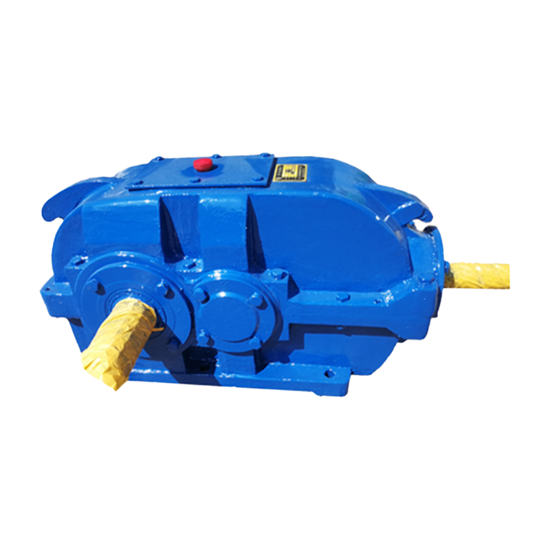 Hard-Tooth Surface Cylindrical Gear ReducerThe Hard-Tooth Surface Cylindrical Gear Reducer utilizes a gear system manufactured through carburizing, quenching, and gear grinding processes, achieving a tooth surf...View Product →
Planetary Gear Reducers
Planetary reducers achieve higher torque density in a smaller footprint, making them ideal for slewing drives, extruders, and other equipment where space is tight. Their efficiency is also high, but the calculator should include the specific stage ratio limit. For a deeper look at planetary technology, see our planetary reducer technical guide.
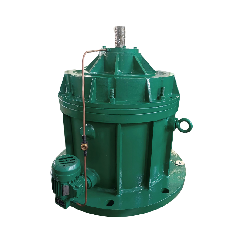 Planetary Gear ReducersA planetary gear reducer is a high-efficiency speed reduction device based on the principle of planetary gear transmission. Its core structure consists of a sun gear, ...View Product →
Worm Gear Reducers
Worm reducers are a compact and economical choice for low-speed applications, especially when the reduction ratio is high. However, their efficiency can be as low as 50% in high-ratio, single-stage designs. This means the output torque gain is not as large as the ratio suggests, and heat becomes a limiting factor. For precise sizing, use the actual efficiency from the catalogue.
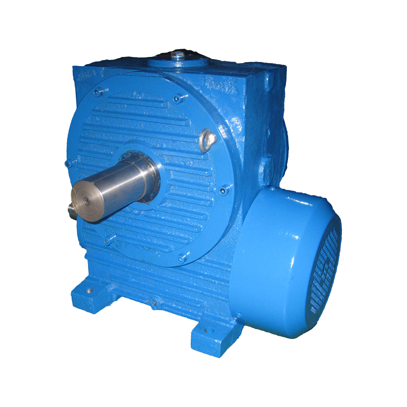 Double-Enveloping Worm Gear ReducerThe Double-Enveloping Worm Gear Reducer employs a unique double-enveloping transmission principle, with a significantly larger meshing area between the worm and worm w...View Product →
Key Selection Factors Beyond the Calculator
The calculator gives you the ideal gear ratio, but a real reducer must also handle shock load, thermal capacity, and efficiency. These factors are often more decisive than the ratio itself. For example, an undersized reducer selected purely on ratio may still fail if the start-up frequency is high or the ambient temperature is elevated. When you are sizing a high-power reducer, pay attention to high-power reducer considerations so that the final design handles thermal limits and lubrication properly.
- Service factor: Use 1.0–1.5 for uniform loads, 1.5–2.0 for moderate shock, and 2.0+ for heavy impact or extremely frequent starts.
- Efficiency: Always use the actual efficiency of the selected reducer type. Multi-stage units have cumulative losses.
- Thermal limit: If the application runs continuously, verify that the reducer can dissipate the heat generated at the rated torque.
FAQ
What is a gear reducer calculator?
A gear reducer calculator is a tool that uses input motor speed, required output speed, and load torque to determine the correct gear ratio, output speed, torque, and service factor.
How do I calculate gear ratio?
Gear ratio equals input speed divided by output speed, or the number of teeth on the driven gear divided by the number of teeth on the drive gear.
Does a higher gear ratio increase torque?
Yes, a higher gear ratio increases torque in proportion to the ratio, but efficiency losses reduce the actual torque at the output shaft.
What service factor should I use for a gear reducer?
Use the manufacturer's recommended service factor based on the driven machine class and daily operating hours; typical values range from 1.0 for uniform loads to 2.0 or more for severe shock loads.
Can a gear reducer calculator handle multi-stage reducers?
Yes, multiply the individual stage ratios to get the total ratio, and include efficiency for each stage to estimate output torque correctly.
Final Insights
Accurate gear reducer calculation is the first step in a reliable drive system, but it is not the only one. You need a manufacturer that can match the calculated ratio with the correct gear hardness, heat treatment, and machining quality. At Taixing Reducer Co., Ltd., we have been producing industrial gear reducers since 1984, with 16 product series and over 10,000 specifications. We use large gear grinding and CNC machining equipment to deliver the precision your application demands. Consider pairing your calculated values with a supplier that offers both standard and custom solutions.