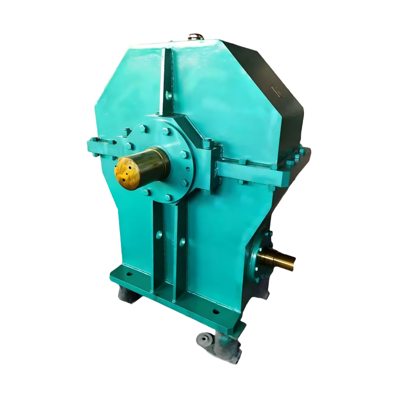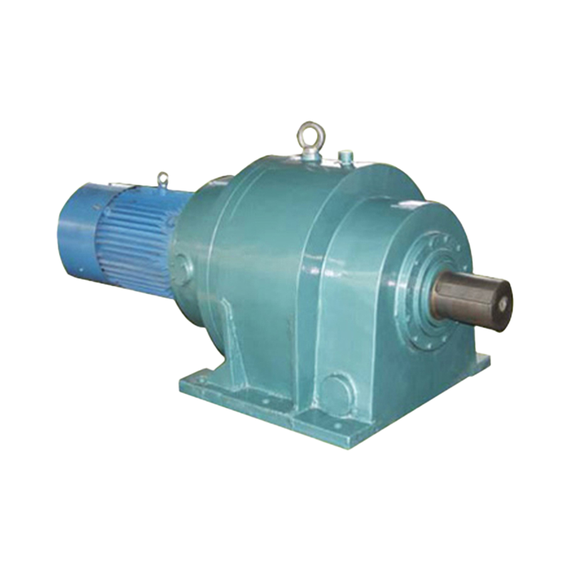
 English
 中文简体
中文简体Your conveyor needs 42 rpm at 5.5 kW, but the catalogue only gives 40 rpm or 45 rpm. The reducer also has to fit behind a swivel bearing and use a hollow output shaft. A standard unit would force you to oversize the motor or redesign the drive cradle. A custom gear reducer is the practical answer when the torque, speed, mounting envelope, or duty cycle cannot be satisfied by a catalogue model.
In short, a custom gear reducer is a gearbox designed and manufactured around your specific ratio, torque, shaft, mounting, and environmental requirements. Done properly, it lowers total cost of ownership because it matches the driven machine's real load instead of relying on an approximate standard selection.
Content
- 1 What Is a Custom Gear Reducer?
- 2 Why Choose a Custom Gear Reducer?
- 3 Key Engineering Specifications to Define
- 4 Types of Custom Gear Reducers
- 5 Applications That Typically Require Custom Reducers
- 6 How to Work with a Custom Gear Reducer Manufacturer
- 7 Custom vs. Standard Gear Reducer: A Practical Comparison
- 8 Cost and Lead Time Considerations
- 9 Frequently Asked Questions
What Is a Custom Gear Reducer?
A custom gear reducer is a speed-reducing gearbox that is engineered for one application rather than selected from a standard product range. It can use different gear types, centre distances, shaft positions, housing shapes, and lubrication systems to fit your machine.
Most custom reducers are not completely new designs. Manufacturers often start with a modular gear platform and adapt the housing, shaft, flanges, oil seal, and ratio. This approach keeps lead time short while still solving your interface and performance problems.
When reviewing options, start with the manufacturer's full product catalogue to identify the closest standard platform, then define the deviations needed for your application. This avoids inventing a gearbox when a modified standard unit would work equally well.
Why Choose a Custom Gear Reducer?
Choose a custom gear reducer when a standard unit cannot satisfy the required ratio, torque, mounting, overload, or environmental resistance without being oversized. Oversizing increases purchase cost, installation space, and energy loss; undersizing causes early gear and bearing failure. A custom design avoids both.
- Ratio mismatch: your process needs an exact output speed such as 42 rpm, not a catalogue average.
- Space constraints: a standard centre distance or shaft extension does not fit the machine frame.
- Shaft arrangement: right-angle output, hollow bore, dual output shafts, or a non-standard hand orientation.
- Severe duty: shock loads, reversing operation, dust, washdown, high ambient temperature, or aggressive atmosphere.
- Thermal limits: the reducer must run continuously without an external cooler, so gear loss must be minimized.
- Retrofit: an old machine has a specific mounting bolt pattern, shaft key, and position, and you want to replace the gear unit without redesigning the equipment.
Key Engineering Specifications to Define
Before requesting a quote, define load class, input speed, output speed or ratio, required torque, service factor, and installation position. If you need a quick refresher on the underlying mechanism, see this explanation of how industrial gear reducers work. The most important point is to give the manufacturer the duty cycle of the driven machine, not just a power rating.
| Parameter | Typical value or note |
|---|---|
| Required torque | Nm or ft-lb at the output shaft, including starting and peak torque |
| Output speed or ratio | e.g., 42 rpm or 20.4:1; state whether ratio tolerance is ±1% or ±0.1% |
| Input speed | e.g., 1460 rpm from a standard AC motor |
| Service factor | 1.25, 1.5, 1.75, or 2.0, depending on load class and hours per day |
| Duty cycle | Continuous, intermittent, frequent starts, reversing, emergency stops |
| Shaft arrangement | Parallel shaft, right-angle, hollow bore, splined output, or double output |
| Mounting | Foot, flange, shaft-mounted, or vertical/horizontal orientation |
| Environment | Indoor/outdoor, ambient temperature range, humidity, dust, washdown chemicals |
The output torque value usually matters more than motor power because the same power can produce very different torque at different speeds. Provide the exact expected operating hours, including overload events.
Types of Custom Gear Reducers
The best type is the one that matches the application's load characteristics and allowable envelope; a wrong topology often leads to oversized gears or short bearing life. The following three configurations cover most customized industrial drives.
Helical Cylindrical Gear Reducers
Helical cylindrical gear reducers are the default for heavy continuous industrial duty because they combine high efficiency, low noise, and good radial load capacity. When the parallel-shaft envelope is constrained, a custom hardened-tooth-surface cylindrical gear reducer can be supplied with the exact centre distance, shaft extension, and mounting flange your machine needs.
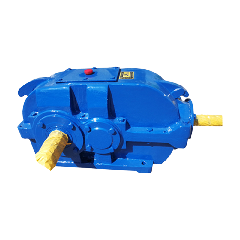 Hard-Tooth Surface Cylindrical Gear Reducer Manufacturer, FactoryTaixing Reducer is a China Hard-Tooth Surface Cylindrical Gear Reducer manufacturer & factory, with years of experience in industrial spe...View Product →
Planetary Gear Reducers
Planetary gear reducers are chosen when you need high torque density and compact integration. A custom planetary gear reducer uses multiple planet wheels to share the radial load, which produces high reduction ratios without a bulky parallel-shaft stage. This topology is common for slew drives, winches, and rotary index tables.
Worm Gear Reducers
Worm gear reducers are the practical answer for right-angle drives with moderate efficiency and a self-locking feature. A custom double-enveloping worm gear reducer increases the contact area between the worm and wheel, so it can handle a higher torque in the same housing size. For a compact right-angle drive with a specific ratio and mounting layout, a custom double-enveloping worm gear reducer is a reliable solution.
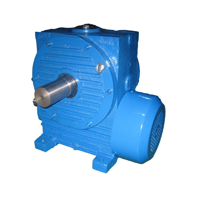 Double-Enveloping Worm Gear Reducer Manufacturer, FactoryTaixing Reducer is a China Double-Enveloping Worm Gear Reducer manufacturer & factory, with years of experience in industrial speed reduc...View Product →
Applications That Typically Require Custom Reducers
Custom gear reducers appear most often in mining, metallurgy, cranes, and material-handling systems where the duty cycle is severe and the envelope is fixed. In these environments, a one-size-fits-all reducer is either too bulky, too weak, or impossible to connect.
- Mining and bulk handling: conveyor reducers with a specific drive pulley arrangement, or a stacker/reclaimer gearbox with a large hollow bore.
- Steel and metallurgy: rolling mill reducers with frequent reversing, ladle turret units, and pipe piercing drives.
- Crane and hoisting: crane travel reducers with spring-loaded brakes, gate hoist reducers with self-locking worms.
- Power and cooling: cooling tower fan reducers designed for vertical shaft installation and outdoor weather resistance.
- Special machines: tension levelers, weigh feeders, disc feeders, and soft-start units that must fit into a process line without redesign.
When the application is compact and weight-sensitive, such as a slew drive or a winch drum, a custom planetary gear reducer delivers a high ratio in a short cylindrical package.
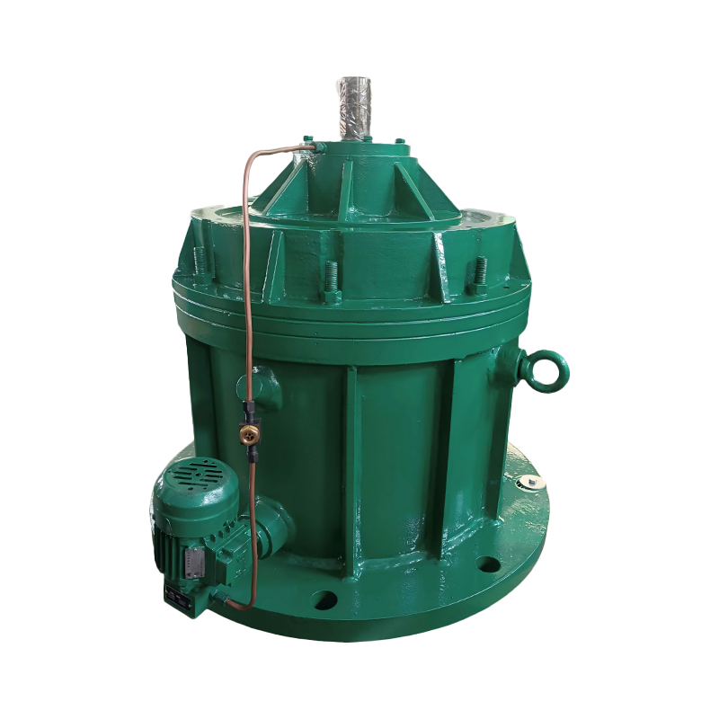 Planetary Gear Reducers Manufacturer, FactoryTaixing Reducer is a China Planetary Gear Reducers manufacturer & factory, with years of experience in industrial speed reducer. Wholesal...View Product →
How to Work with a Custom Gear Reducer Manufacturer
A reliable custom reducer project follows a disciplined workflow: application data sheet, preliminary design, torque and thermal check, drawing review, and then production.
- Submit an application data sheet with torque, speed, duty, mounting, and environment details.
- The manufacturer selects gear topology, material, heat treatment, and bearing arrangement.
- A load analysis verifies gear bending strength, contact stress, bearing life, and thermal capacity.
- You review the general arrangement drawing and confirm shaft sizes, keyways, mounting holes, and oil fill/vent positions.
- For high-volume or critical applications, prototypes are tested under load before series production.
- Production includes gear cutting, grinding, assembly, run-in testing, and measurement of vibration, noise, and temperature.
Working with a factory that has large grinding and hobbing capability reduces tolerance risk on big-diameter gears. In particular, a 3-meter gear grinder and a 3.2-meter hobbing machine allow hardened tooth profiles to be finished accurately even for large non-standard centre distances.
Custom vs. Standard Gear Reducer: A Practical Comparison
The main difference is application fit versus price: a standard reducer costs less and has a short lead time, while a custom reducer gives better life and energy performance when the standard envelope is wrong. The table below summarises the trade-offs for decision-making.
| Aspect | Standard reducer | Custom gear reducer |
|---|---|---|
| Initial cost | Lower | Higher |
| Lead time | Short, from stock or assembled | Longer, includes design and machining |
| Efficiency | Optimized for a catalogue range | Can be optimized for your duty point |
| Torque density | May be oversize for the load | Matched to required torque and service factor |
| Mounting flexibility | Limited to standard feet/flanges | Shafts, flanges, and mountings tailored to your layout |
| Bearing life | Calculated for a general duty range | Verified for the exact load spectrum |
| Maintenance | Easy spare parts access | Nominally less common, but fewer adapters |
Cost and Lead Time Considerations
Expect a custom gear reducer to cost more and take longer than a standard unit, but the premium is justified when it extends equipment life or avoids redesigning the driven machine. The main cost drivers are engineering input, low-volume manufacturing, and non-standard tooling or heat treatment.
- Engineering time: each design needs load calculations, drawings, and drawing approval.
- Gear cutting and grinding: custom gears use dedicated blanks and are processed to your specified hardening profile.
- Tooling and patterns: special cast-iron housings may require new patterns or one-off fabrication.
- Testing and certification: load testing, material certificates, and dimensional reports add cost.
To control the budget, keep the rest of the interface standard: use a conventional foot or flange mounting, avoid exotic materials unless required, and provide the exact motor data at the start. A modular platform design can reduce the extra cost by using internal gear sets and bearing arrangements that are already proven, rather than starting from a blank sheet.
Frequently Asked Questions
What information should I have before asking for a custom gear reducer?
The minimum is output torque, output speed or ratio, input speed, service factor, duty cycle, shaft arrangement, mounting style, and ambient conditions. Without those data, a manufacturer can only estimate, which often leads to a design that is oversized or under-engineered.
Can I order just one custom gear reducer?
Yes. Many gearbox factories accept one-off orders, but the engineering and pattern cost makes a single unit more expensive than a batch. If your budget is tight, ask whether an existing standard unit can be modified with a special shaft or flange.
Is a custom reducer harder to maintain?
No, not necessarily. The maintenance schedule depends on bearing selection, lubrication, and sealing. If you use standard oil seals and bearings where possible, spare parts remain easy to source. A clean custom design with proper breathers and drains may be even easier to service because it is sized for real loads.
How long does a custom gear reducer last?
With the correct service factor and maintenance, expected design life is typically 5 to 10 years for continuous industrial duty, and much longer for lighter duty cycles. Ask the manufacturer for a calculated L10 bearing life and a gear safety factor based on your load profile.
Bottom line: a custom gear reducer is not the first option for every application, but when torque density, duty cycle, or installation geometry demand it, working with an experienced manufacturer on a clearly specified design is the fastest way to a reliable drive. Start with the application data, review the closest standard platform, and then decide exactly which dimensions and performance requirements need to be changed.