 English
 中文简体
An industrial gearbox is the general term for any enclosed gear train that transmits power between a motor and driven equipment. A gear reducer is a specific kind of gearbox that is built to lower output speed and multiply output torque. In short, every gear reducer is a gearbox, but not every gearbox is a gear reducer.
Maintenance engineers and procurement teams frequently use the two terms as synonyms, and in many catalogs they refer to the same housing, gears, and bearings. The distinction does not change the way gears mesh, but it changes how you define the design goal. When you specify a reducer, you commit to a ratio greater than one and to a torque gain. When you specify a gearbox, you must state whether the input speed stays the same, rises, falls, or changes direction before the unit can be sized correctly.
Content
Gearbox vs. Gear Reducer: Definitions and Core Differences
The conclusion first: a gearbox is the parent category, and a gear reducer is one of its most common sub-types. A gearbox can contain any pair of meshing gears for any purpose — matching speeds, reversing rotation, converting torque, or splitting power among several outputs. A gear reducer, also called a speed reducer or reduction gear, is a gearbox with an input-to-output speed ratio greater than one, so it always reduces speed and increases torque.
This distinction appears clearly in how engineers describe the two pieces of equipment on a motor and drive train:
| Comparison point | Gearbox | Gear Reducer |
|---|---|---|
| Definition | Any enclosed gear train that transmits power | A gearbox optimized to reduce speed and increase torque |
| Speed ratio | Can be 1:1, greater than 1, or less than 1 | Always greater than 1 |
| Output speed | May be equal to, faster than, or slower than input speed | Always slower than input speed |
| Output torque | Depends on the gear arrangement | Always higher than input torque |
| Common names | Gear unit, transmission, gear housing | Speed reducer, reduction gear, worm reducer, planetary reducer |
| Typical use | Power transmission, direction change, speed matching | Torque multiplication for heavy industrial loads |
If you look at a nameplate, the unit may even be labeled with both terms because manufacturers know that the two words are used in the same context. The useful question is not which word to print on the purchase order, but what the unit must actually do between the motor and the machine.
Why the Difference Matters in Real Buying Decisions
Treating a reducer as a generic gearbox causes more specification errors than almost any other mistake in drive selection. The reason is that the ratio defines the torque multiplication, and torque is the number that determines gear size, shaft diameter, bearing life, and housing strength.
The practical effects show up in four areas:
- Ratio definition: a gearbox request without a ratio leaves the door open for a 1:1 unit or a speed-increasing unit, while a reducer request forces a ratio such as 10:1 or 25:1 to be calculated from the required output speed.
- Torque output: a reducer is chosen by multiplying the motor torque by the ratio and applying a service factor; a gearbox is often chosen for speed or direction only.
- Number of stages: reducers commonly need two or three stages to reach high ratios, which directly affects efficiency and heat generation.
- Spare parts: when one unit fails, ordering a "gearbox" without the reducer designation risks getting a unit with the same footprint but a different ratio class.
For most industrial installations, the cost difference between the two descriptions is less important than the downtime that follows a mismatch. That is why experienced purchasing engineers define the gearbox or reducer by its ratio, torque rating, mounting position, and input speed before opening a catalog.
Common Types of Gear Reducers
Gear reducers come in four main types — helical, planetary, worm, and cycloidal — and each trades efficiency, ratio, and size differently. To make the right choice, it helps to understand how an industrial gear reducer works and which type is used for a given duty.
Helical and Cylindrical Gear Reducers
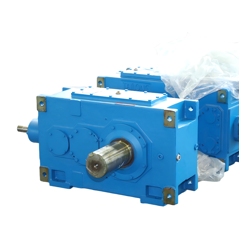
Helical gear reducers use parallel shafts with angled teeth, which creates smooth, quiet contact and good efficiency, typically 95–98% per stage. Cylindrical gear reducers dominate conveyor, mixer, crane, and hoisting applications because they handle high radial loads and can be produced in very large sizes. A hardened tooth surface cylindrical gear reducer, for example, offers long service life in dusty or shock-loaded environments such as mining and cement plants.
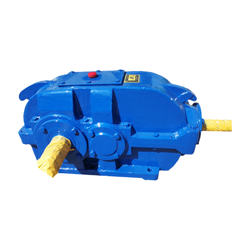 Hard-Tooth Surface Cylindrical Gear Reducer for Heavy-Duty UseThis hardened gear reducer uses carburized and ground teeth with 58-62 HRC surface hardness, improving load capacity and service life. It suits dusty, shock-loaded environments like mining and cement plants while handling high radial loads.View Product →
Planetary Gear Reducers
Planetary reducers concentrate torque in a compact shell by distributing the load among several planet gears around a central sun gear. They achieve high ratios, often from 3:1 up to more than 100:1, with efficiency that can reach 97% per stage, and they offer excellent torque density for servo drives and heavy-duty rotation. Designs such as NGW-type planetary gear reducers are widely used when mounting space is limited but torque demand is high.
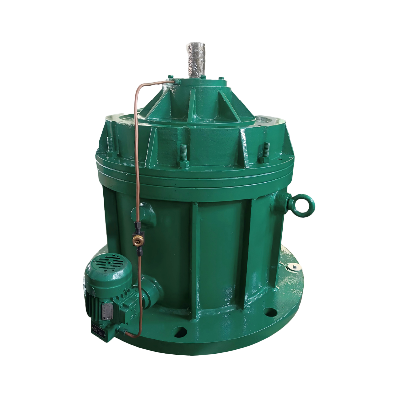 Planetary Gear Reducers for High Torque Density and PrecisionWith a coaxial multi-gear load-sharing design, these reducers achieve single-stage efficiency above 97% and reduced size and weight. Ideal for space-limited servo drives, robots, and heavy-duty rotation requiring precise positioning.View Product →
Worm Gear Reducers
Worm reducers use a worm screw that drives a worm wheel on a perpendicular shaft. One stage can deliver high ratios — typically from 5:1 to 60:1 — with a compact right-angle arrangement and the possibility of self-locking, which prevents back-driving in hoisting applications. The trade-off is lower efficiency, usually 50% to 85%, so worm reducers suit intermittent duty and moderate power better than continuous high-horsepower service. A double-enveloping worm gear reducer improves the contact area and raises load capacity compared with a single-enveloping unit.
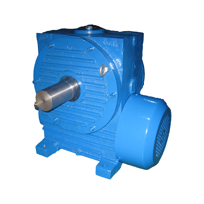 Double-Enveloping Worm Gear Reducer with Enhanced Load CapacityThis right-angle reducer increases tooth contact area by over 30% versus ordinary worm units, lowering stress and backlash within 10 arc minutes. It suits low-speed, heavy-load precision control in dusty or humid industrial settings.View Product →
Cycloidal Reducers
Cycloidal reducers replace conventional gear teeth with rolling pins and a cycloidal disc, giving them high shock-load capacity, compact size, and very low backlash. They are common where positioning precision and impact resistance matter, such as indexing tables and material handling equipment.
| Type | Typical ratio range | Efficiency range | Best suited for |
|---|---|---|---|
| Helical / cylindrical | 1:1 to ~100:1 | 95–98% | Conveyors, cranes, mixers, heavy industrial drives |
| Planetary | 3:1 to 100+:1 | 92–97% | Compact high-torque drives, servo and mobile equipment |
| Worm | 5:1 to 60:1 | 50–85% | Right-angle drives, intermittent duty, self-locking needs |
| Cycloidal | 6:1 to 87:1 | 90–95% | Shock loads, precise indexing, compact installations |
How to Choose Between a Gearbox and a Gear Reducer
Choose a gearbox when your drive needs speed matching, direction change, or power splitting. Choose a gear reducer when the core requirement is a fixed reduction ratio and higher output torque. If you already know that the motor runs too fast for the machine, you are buying a reducer, not a generic gearbox.
Work through the selection in this order:
- Calculate the ratio: divide the motor speed by the required output speed, then round to the nearest standard ratio.
- Calculate the output torque: multiply the motor torque by the ratio, then apply a service factor that accounts for shock loads and daily operating hours.
- Choose the geometry: parallel shafts usually mean cylindrical reducers, concentric shafts mean planetary, and right-angle needs point to worm or bevel units.
- Check the efficiency: if the drive runs 24 hours per day, the difference between 80% and 97% efficiency can change operating cost dramatically.
- Verify mounting and environment: foot, flange, hollow-shaft, dust, humidity, and ambient temperature all influence the housing design and lubrication.
Applications also point to a natural winner. Lifting and hoisting drives benefit from the self-locking capability and high ratio of a worm reducer. Continuous production lines favor the efficiency and durability of a hardened cylindrical reducer. High-precision positioning favors a planetary design. Severe impact loads favor cycloidal construction.
When the terminology still feels unclear, remember that manufacturers catalog these units by reduction ratio and torque rating, so the fastest way to a correct order is to copy the same parameters from your machine nameplate or motor datasheet.
FAQ
Is a speed reducer the same as a gearbox?
A speed reducer is one type of gearbox. The term gearbox also covers speed increasers, reversing gearboxes, and 1:1 power take-offs, while a speed reducer always has a ratio greater than one.
Can a gearbox increase speed?
Yes. A gearbox with a ratio less than one acts as a speed increaser — the output turns faster than the input and torque drops accordingly. Such units are sometimes used in generators and high-speed testing equipment. A gear reducer cannot increase speed by definition.
Which is more efficient, a worm reducer or a planetary reducer?
Planetary reducers are almost always more efficient, with values in the mid-90s per stage, while worm reducers often sit between 50% and 85% depending on ratio and lubrication. For continuous operation, planetary is usually the better energy choice.
Why do some reducers use multiple stages?
One gear pair can only reduce speed by a limited amount before the gear becomes too large. Manufacturing a dozen gear pairs all contributing to the same reduction offers a compromise between efficiency, size, and cost.
Conclusion
A gear reducer is a gearbox, but one built for a single purpose: turning speed into torque. Use the term gearbox when you need any gear-based transmission, and use gear reducer when you need a defined reduction ratio and higher output torque. The practical specification must always include the ratio, torque rating, efficiency class, and mounting geometry.
Once those parameters are set, the choice between helical, planetary, worm, and cycloidal construction becomes an engineering decision based on load, duty cycle, and space. Defining the function first — reduction versus simple transmission — removes most of the ambiguity and helps you order the right unit the first time.