
 English
 中文简体
中文简体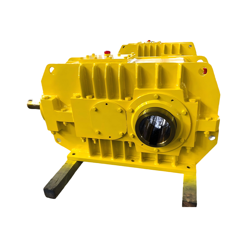
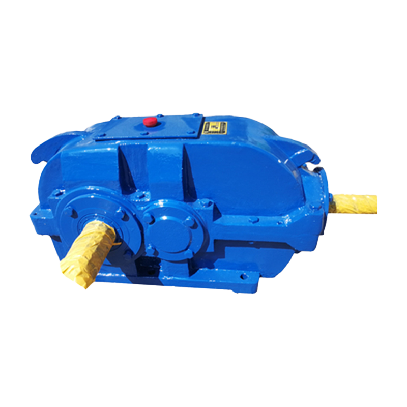
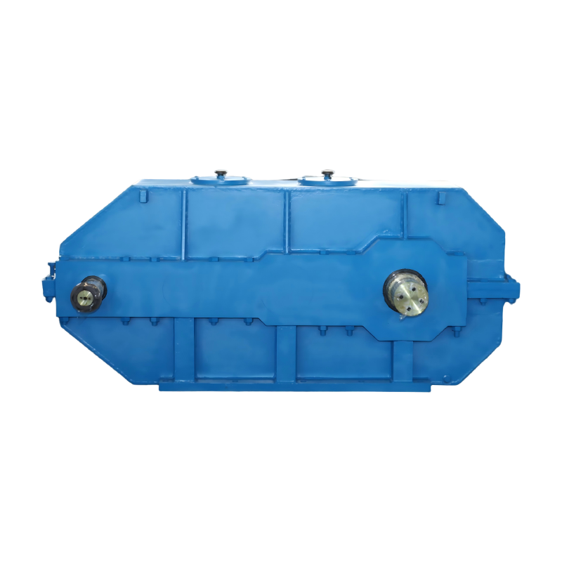
As a China Cylindrical Gear Reducers Manufacturer and Custom Cylindrical Gear Reducers Supplier, Taixing Reducer Co., Ltd. was founded in 1984 and is a specialized manufacturer dedicated to the research, development, and production of industrial gear reducers. The company covers an area of 300,000 m², with fixed assets of RMB 380 million and more than 2,000 employees, including 186 engineering and technical professionals. With decades of manufacturing experience, Taixing has developed strong capabilities in reducer design, production, and application integration, providing reliable transmission solutions for a wide range of industrial sectors.
Advanced Manufacturing
Taixing continuously invests in advanced production equipment and technologies. The company has introduced high-precision machinery from Germany, Russia, and the United States, including large gear grinding machines, gear hobbing machines, vertical lathes, and CNC machining centers. To meet the growing demand for large-scale reducers, the company has also installed equipment such as 3-meter gear grinding machines, 3.2-meter gear hobbing machines, and large-scale boring and milling centers, ensuring high precision and stable product performance.
Product Strength
As a specialized reducer manufacturer, Taixing offers 16 major product series and more than 10,000 specifications, with an annual production capacity of 200,000 units. The company focuses on product innovation and quality control, achieving a 99.8% customer satisfaction rate. Its products are designed to meet high industry standards, ensuring low noise, high efficiency, and reliable operation. Several independently developed reducers, including the TXP, NBD, NCD, and three-ring series, have gained strong recognition from the market.
Quality & Brand Commitment
The company strictly controls product quality and production processes to ensure every reducer meets high reliability and durability standards. The Taixing brand reducer has been widely recognized in China and has been used in numerous key national projects and large industrial enterprises.
Customer-Oriented Philosophy
Through continuous innovation and reliable service, Taixing is committed to delivering high-performance reducer solutions and building long-term partnerships with customers worldwide.
Cylindrical Gear Reducers Manufacturer
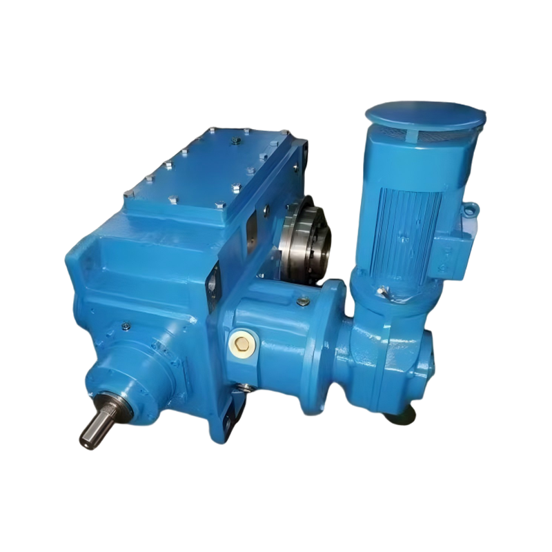
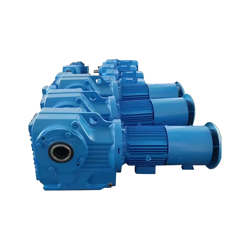
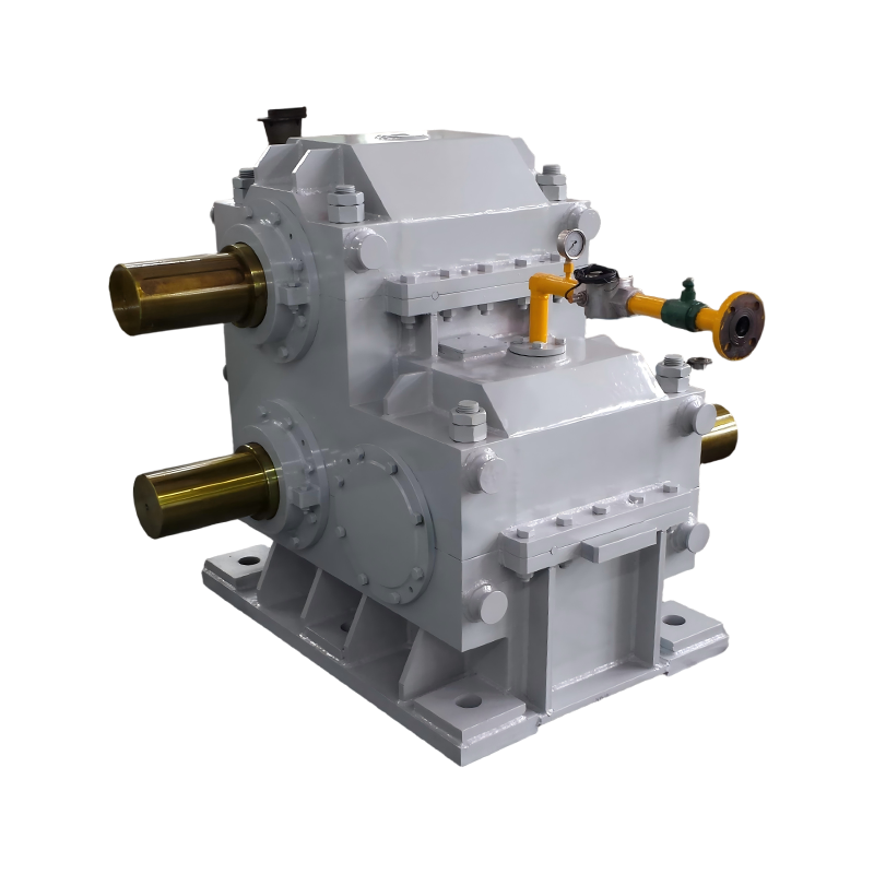
Cylindrical gear reducers are a type of power transmission mechanism that use gears as speed converters to reduce the rotation speed of a motor to the desired speed, while obtaining a larger torque. The gears of this reducer are carburised, quenched and ground, providing high load capacity and low noise. Cylindrical gear reducers are widely used in metallurgy, mining, lifting, transportation, cement, construction, chemical, textile, dyeing, and pharmaceutical sectors.
About Us
TAIXING REDUCER CO., LTD.
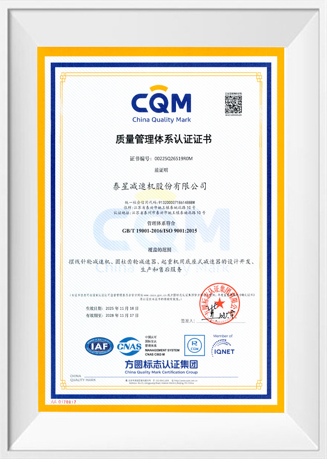
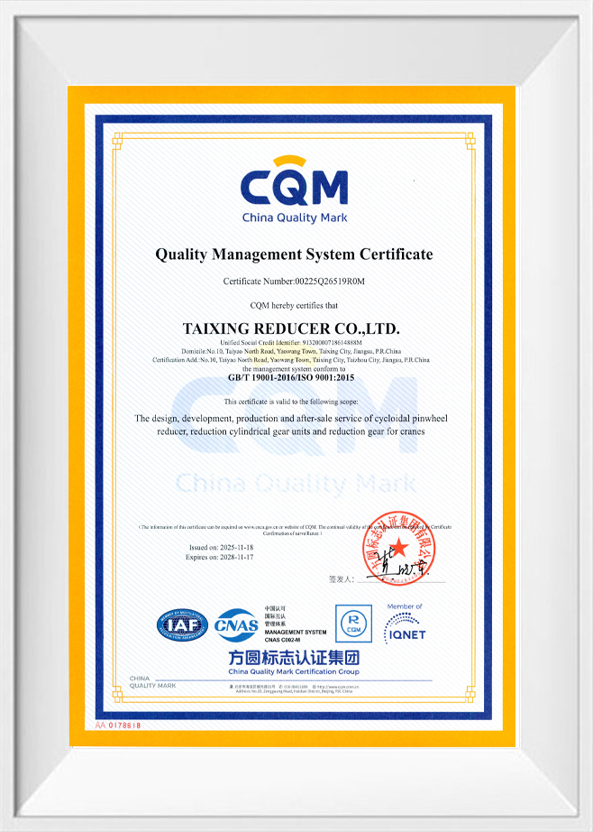
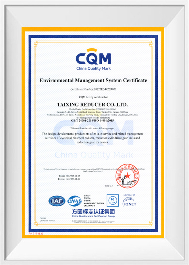
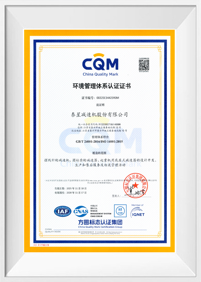
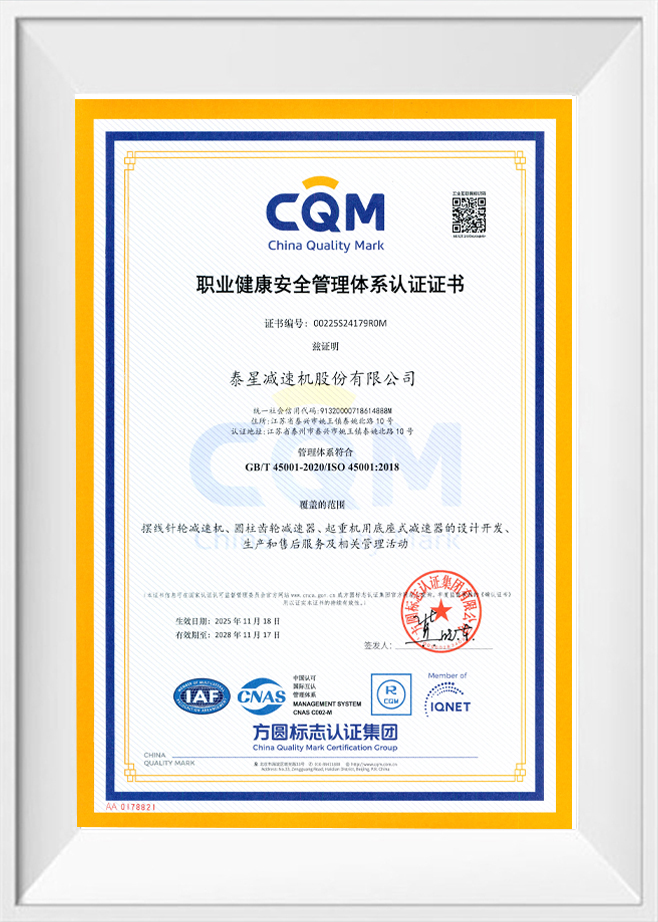
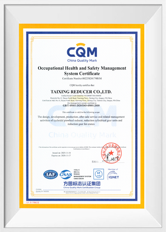
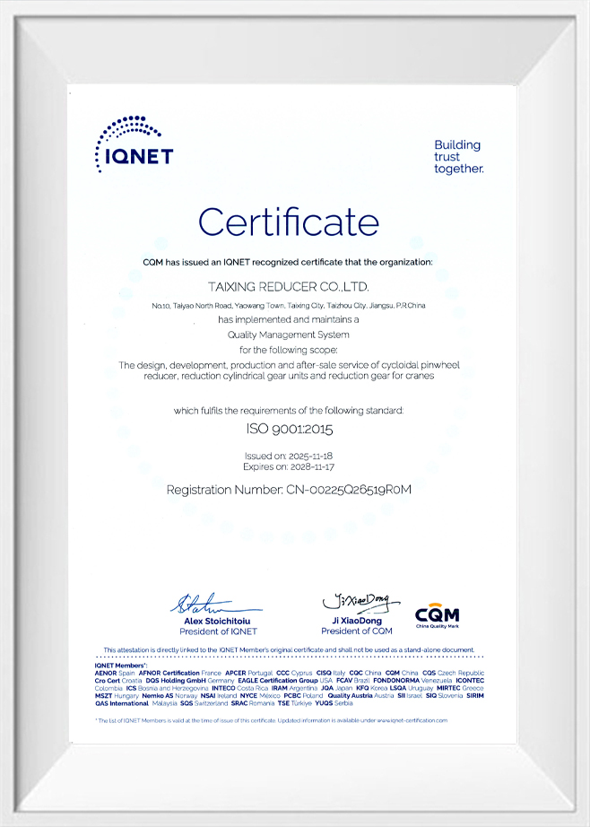
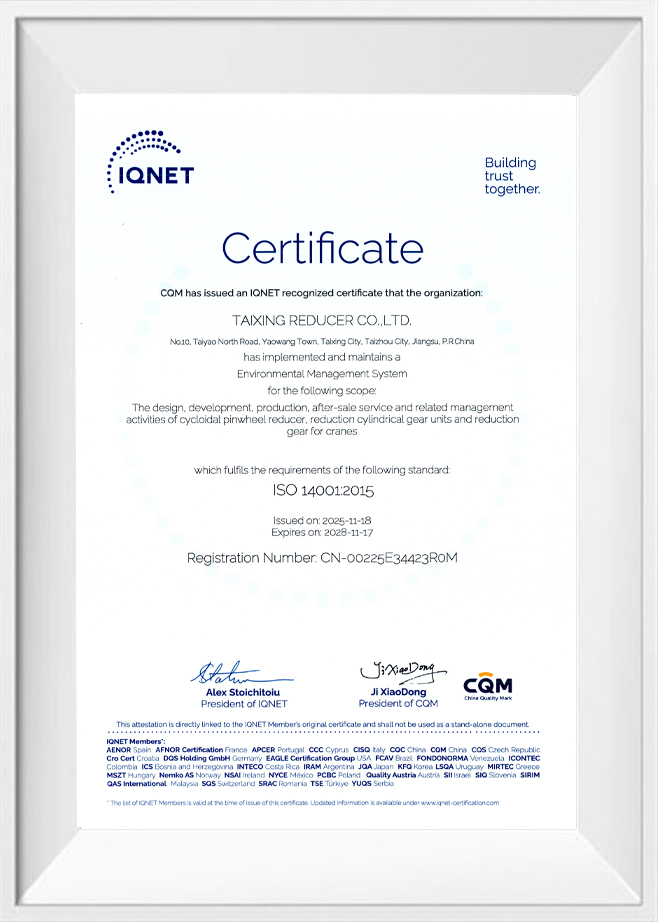
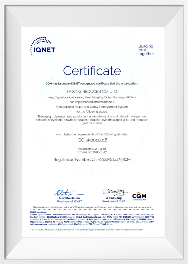
Certificate Of Honor
News
-
Choosing a gear reducer starts with a load number, not a catalog page. The load number is the output torque your drive...
READ MORE -
Your conveyor needs 42 rpm at 5.5 kW, but the catalogue only gives 40 rpm or 45 rpm. The reducer also has to fit behin...
READ MORE -
What Is an Extruder Hardened Gear Reducer? An extruder hardened gear reducer is a heavy-duty speed reducer with case-h...
READ MORE -
What a Right Angle Gear Reducer Is and When to Specify One A design engineer walks along a conveyor line and sees the m...
READ MORE -
To preload a worm gear reducer, you must apply a controlled internal force that eliminates the clearance between the wo...
READ MORE -
Attaching a gear reducer to an electric motor is a fundamental task in mechanical power transmission. The most common a...
READ MORE -
A planetary gear reducer directly enhances robotics performance by multiplying motor torque while maintaining high tors...
READ MORE -
To select the right bearing for a gear reducer, you must match the bearing type and size to the specific radial and axi...
READ MORE
Message Feedback
Cylindrical Gear Reducers Industry knowledge
What Is a Cylindrical Gear Reducer
A cylindrical gear reducer is a gear transmission device in which the gear shafts are arranged in parallel, and power is transmitted through spur or helical gears mounted on cylindrical gear blanks. This is one of the most widely used reducer configurations in industrial power transmission due to its relatively simple structure, high transmission efficiency, and broad range of available torque and ratio combinations.
Taixing Reducer Co., Ltd., founded in 1984, has produced cylindrical gear reducers as part of its core product range, drawing on decades of experience in gear design, manufacturing, and application integration across multiple industrial sectors.
Structural Principle
In a cylindrical gear reducer, input and output shafts are positioned parallel to one another, connected through one or more pairs of meshing gears mounted in series. Each gear pair forms a reduction stage, and the overall ratio of a multi-stage unit is the product of the ratios of its individual stages. Gear teeth may be cut as spur gears, which have teeth parallel to the shaft axis, or helical gears, which have teeth cut at an angle to provide smoother engagement and reduced noise during operation.
Key Performance Characteristics
- High Transmission Efficiency: Parallel-shaft gear meshing generally results in lower power loss compared with some other gear configurations such as worm gearing.
- Wide Torque Range: Available in a broad range of sizes, supporting both light-duty and heavy-duty applications.
- Multi-Stage Flexibility: Additional gear stages can be incorporated to achieve higher reduction ratios within practical housing dimensions.
- Stable Operation: Helical tooth designs provide continuous gear engagement, which contributes to smoother running and reduced vibration.
Common Types of Cylindrical Gear Reducers
| Type | Structural Feature | Typical Use Case |
| Single-Stage Cylindrical Reducer | One pair of meshing gears | Applications requiring moderate reduction ratios |
| Two-Stage Cylindrical Reducer | Two gear pairs connected in series | Applications requiring higher reduction ratios |
| Multi-Stage Cylindrical Reducer | Three or more gear pairs in series | Heavy-duty applications requiring large reduction ratios and high torque output |
| Parallel-Shaft Helical Reducer | Helical gears on parallel shafts | Applications requiring smoother operation and reduced noise |
Cylindrical Gear Reducer vs. Worm Gear Reducer
| Aspect | Cylindrical Gear Reducer | Worm Gear Reducer |
| Transmission Efficiency | Generally higher due to parallel-shaft gear meshing | Generally lower due to sliding contact between worm and wheel |
| Shaft Arrangement | Parallel shafts | Perpendicular shafts |
| Reduction Ratio per Stage | Moderate per stage, requiring multiple stages for high ratios | Can achieve higher ratios within a single stage |
Typical Application Sectors
- Metallurgy and Mining: Used in conveyors, crushers, and material processing equipment where reliable, high-efficiency transmission is required.
- Cement and Building Materials: Applied in mills and rotary equipment within production lines.
- Power Generation: Used in auxiliary equipment such as cooling towers and material handling systems.
- Chemical and Petrochemical Processing: Applied in mixers, agitators, and pumps within process systems.
- Ports and Material Handling: Used in cranes and bulk conveying systems requiring stable, continuous-duty transmission.
Key Technical Parameters for Selection
| Parameter | Description |
| Reduction Ratio | Ratio between input and output rotational speed across all stages |
| Output Torque | Maximum torque delivered at the output shaft |
| Number of Stages | Number of gear pairs connected in series within the unit |
| Gear Tooth Type | Spur or helical tooth design, affecting noise and load distribution |
| Mounting Configuration | Foot-mounted, flange-mounted, or shaft-mounted arrangement |
Manufacturing Considerations
The performance of a cylindrical gear reducer depends on accurate gear-tooth profile machining, proper heat treatment, and precise shaft and bearing alignment during assembly. These factors affect load distribution across the gear teeth, noise levels, and long-term durability under continuous operation.
Taixing Reducer has invested in high-precision machinery sourced from Germany, Russia, and the United States, including gear grinding machines, gear hobbing machines, vertical lathes, and CNC machining centers, to support consistent manufacturing quality. For large-module cylindrical gear components, the company has also installed equipment such as 3-meter gear grinding machines, 3.2-meter gear hobbing machines, and large-scale boring and milling centers, supporting the production of heavy-duty, large-scale reducer units.
Maintenance Considerations
- Lubrication Management: Regular inspection of lubricant level and condition based on operating duty cycle.
- Gear Wear Inspection: Periodic checks for abnormal wear patterns on gear tooth surfaces.
- Bearing Condition Monitoring: Vibration and temperature checks to detect early signs of bearing wear.
- Seal Inspection: Checking shaft seals and housing joints for oil leakage.
Frequently Asked Questions
How is the appropriate number of gear stages determined?
The number of stages is generally determined by the required overall reduction ratio. Higher ratios typically require additional stages, since each individual gear pair has a practical limit on the ratio it can achieve while maintaining structural and meshing efficiency.
What is the difference between spur and helical gear tooth types?
Spur gears have teeth parallel to the shaft axis and engage one tooth pair at a time, while helical gears have angled teeth that engage gradually. This gradual engagement in helical gears typically results in smoother operation and reduced noise compared with spur gears.
Are cylindrical gear reducers suitable for heavy-duty industrial applications?
Cylindrical gear reducers are widely used in heavy-duty applications such as mining, metallurgy, and cement processing. Large-module units manufactured with appropriate precision equipment can support high torque and continuous-duty operating conditions.

Contact us
-
Factory Address
No. 10, Taiyao North Road, Yaowang Town, Taixing City, Jiangsu Province, China
-
Phone
86-139 5115 9007
Copyright © TAIXING REDUCER CO., LTD. Rights Reserved.
China Cylindrical Gear Reducers Manufacturer Custom Cylindrical Gear Reducers Supplier